The .blend file for this tutorial can be found on GitHub.
Introduction
Put simply, 3D modeling software such as Blender manipulates 3D geometry by pushing around vertices, edges, and faces – as opposed to "proper" CAD, which manipulates logical descriptions of 3D objects. The problem with this approach is that it can be hard to change an object after the fact. A printable boomerang might consist of tens of thousands of vertices and faces, which you do not want to move around one by one.
Luckily, Blender allows for the use of modifiers, which are logical descriptions of operations on the 3D geometry such as "mirror the object along the X axis" or "extrude those faces to form a solid body" which can be stacked upon each other and manipulated after the fact. Using modifiers, we can follow a non-destructive workflow, which means that we are able to construct a triblader boomerang from very simple geometry for one wing, adding modifiers, which allow us to manipulate the detailed boomerang shape with its 40,000 faces in terms of the simplified geometry.
A triblader is extra challenging in this respect because we want its wings to be symmetrical. The problem here is to make use of that symmetry while still being able to edit the shape of the wing. In my previous article, I just copied the wing three times and joined the copies; that approach makes it all but impossible, though, to change the shape of the wing afterwards.
So here's the game plan:
- Model the outline of one wing to our liking
- Create three copies of the wing and put them together into one shape
- Give some thickness to that shape and form the airfoils of the boomerang
- Make things pretty
Scene Setup
Delete the default cube, camera, and light. We don't need those. Set the units to mm (Scene Properties → Units), so we can export the STL in the right size later.

Modeling Wings
Modeling a Single Wing
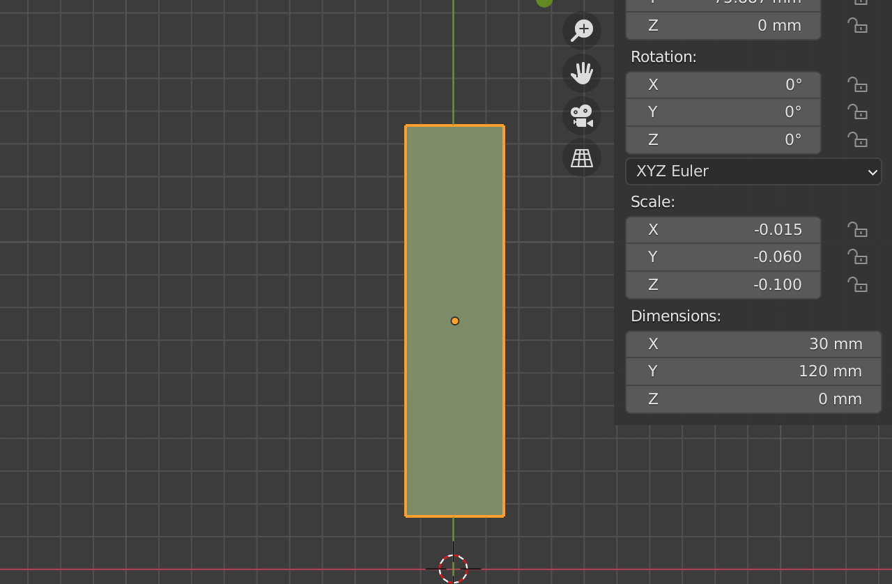
In top view, add a plane and scale it to a reasonable size for one wing (e.g. 120 mm x 30 mm). Apply the scale (Ctrl-A) now, otherwise the following operations will yield strange results.
Subdivide both the length and width using loop cuts (Ctrl-R) or the "Subdivide" command.
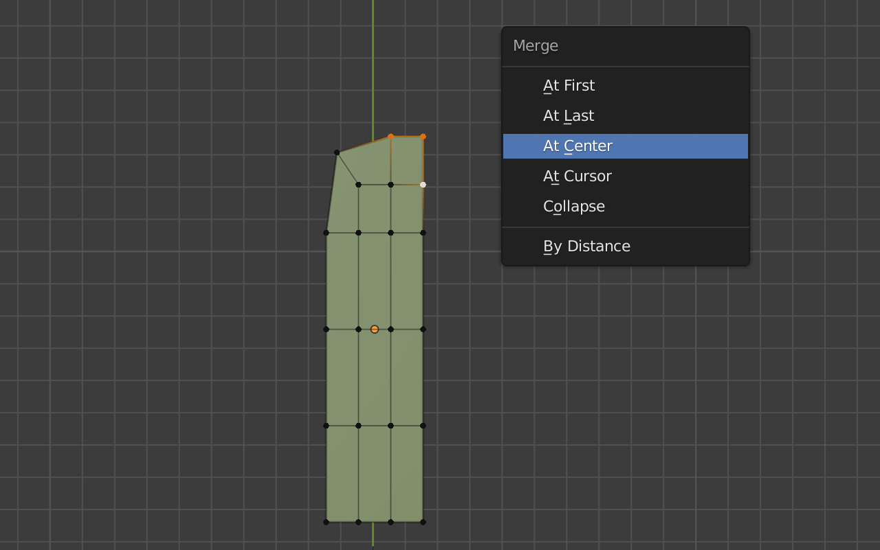
Select three corner vertices in each upper corner and merge those (M). That will be our wing tip. At this point, we can roughly shape our wing and add more topology if needed.

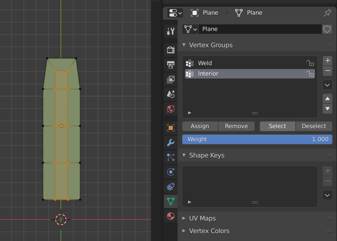
Creating Vertex Groups
For the following operations, we need to mark two groups of vertices: the "weld" vertices are those where we will stitch our boomerang together in the center. The "interior" vertices are those that will make up the top surface of the boomerang.
Blender manages vertex groups for these purposes. So we will create two vertex groups called "Weld" and "Interior" and assign to them the vertice shown here.

Creating More Wings
Creating three wings out of one shape is a bit tricky. We would like to use something like the Mirror modifier, but that one doesn't allow for rotational symmetry. We can achieve something similar though using the Array modifier in combination with a Weld modifier. The former will create our three identical wings, and the latter will fuse those together into one shape.
Add an Array modifier to the wing and create two more copies of it. In order for the copies to be rotated by 120 degrees each, we need to make use of an object offset.
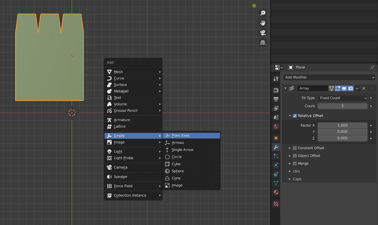
As the offset object, create an empty and rotate it by 120 degrees around the Z axis.
![]()
Remove the relative offset from the array modifier, and use object offset with the empty as the object. This should result in three wings placed at 120 degrees from each other, although they're probably not in the right spot yet.
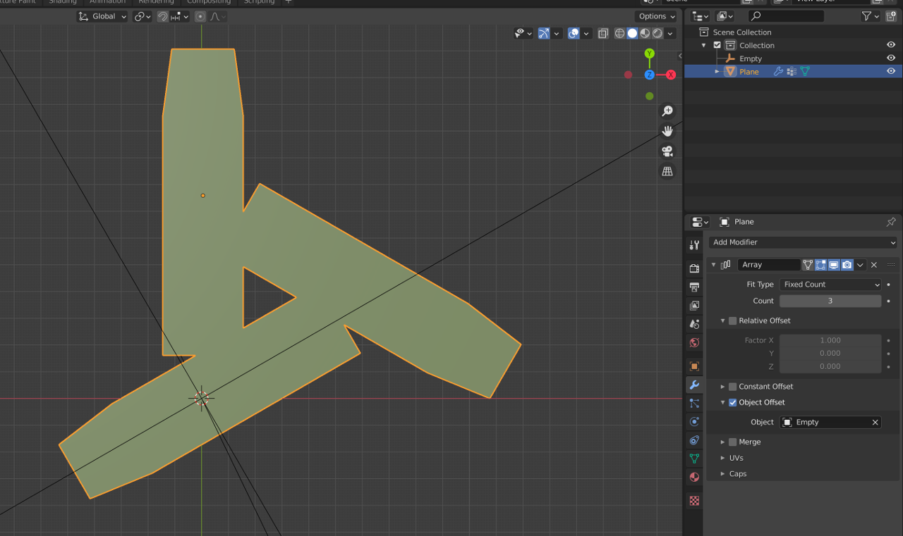
Move around the empty and/or the original wing, so that wings line up around the world origin.
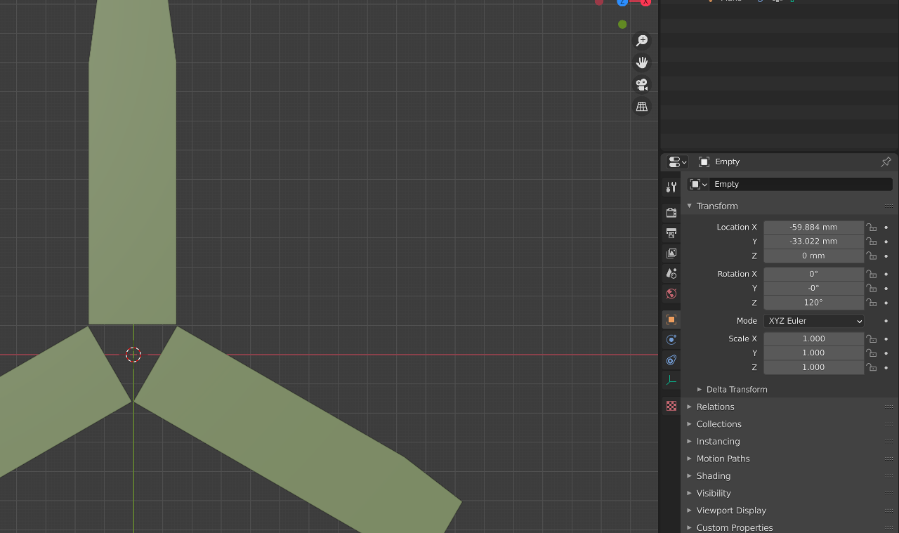
So far, we have three disjoint wings. We need to stitch these together using a Weld modifier, which merges vertices that are close to one another.
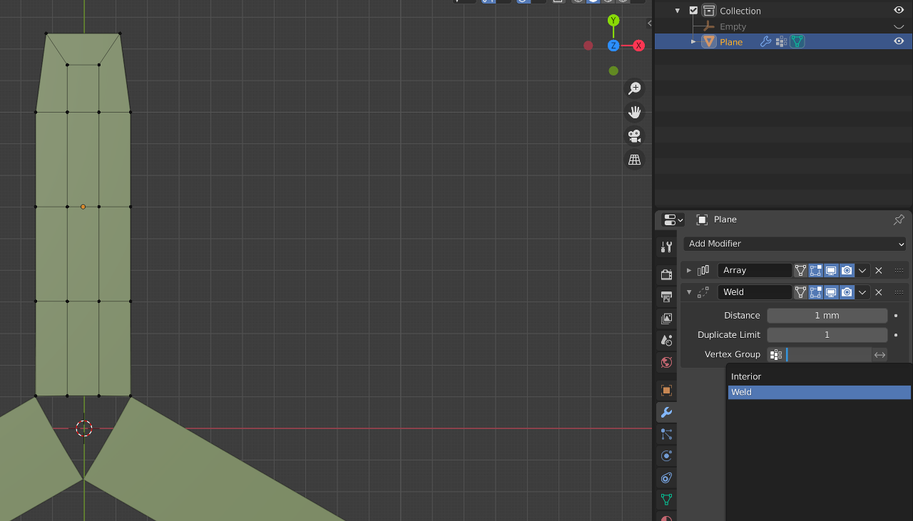
Add a Weld modifier to our object. Constrain it to the vertex group "Weld" that we created earlier. That makes sure that the vertices are only welded in the center where we need it. Set welding distance to 1 mm. This makes sure we do not collapse vertices elsewhere by accident.
Move around the weld vertices so the center of our boomerang goes solid.
Going Three Dimensional
Extruding the Outline
Normally, we would now just extrude the shape to give it thickness. The equivalent modifier is called Solidify. Add a Solidify modifier to our shape. Use the "Simple" method, offset 1, and a thickness of, say, 4 mm.
At that point, we do not have airfoils. We can create those by using the "Interior" vertex group we created earlier in the Solidify modifier, so only those vertices are extruded the full thickness.
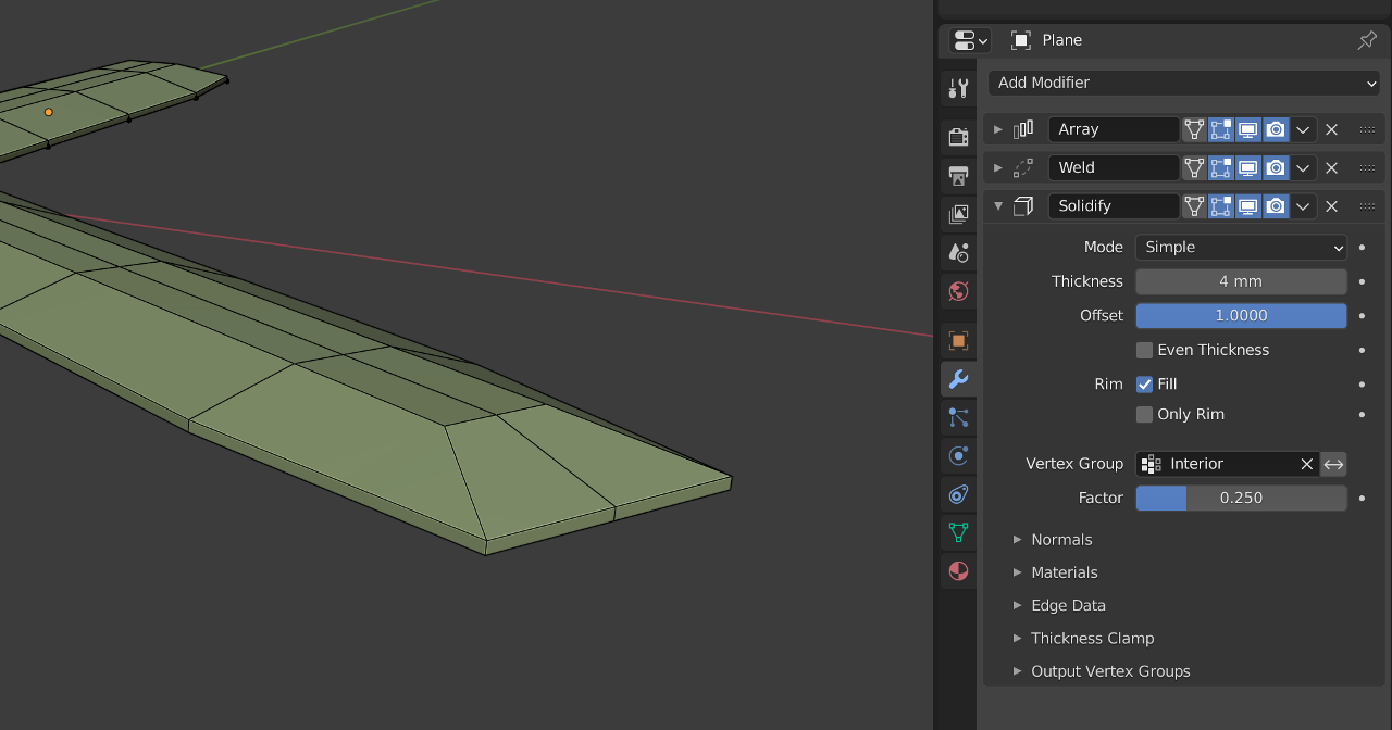
Use the "Factor" setting to determine how much the airfoils will thin down towards the leading and trailing edges. A factor of 0 will mean razor-sharp airfoils, while 1 means no airfoils at all.
Cleaning Things Up
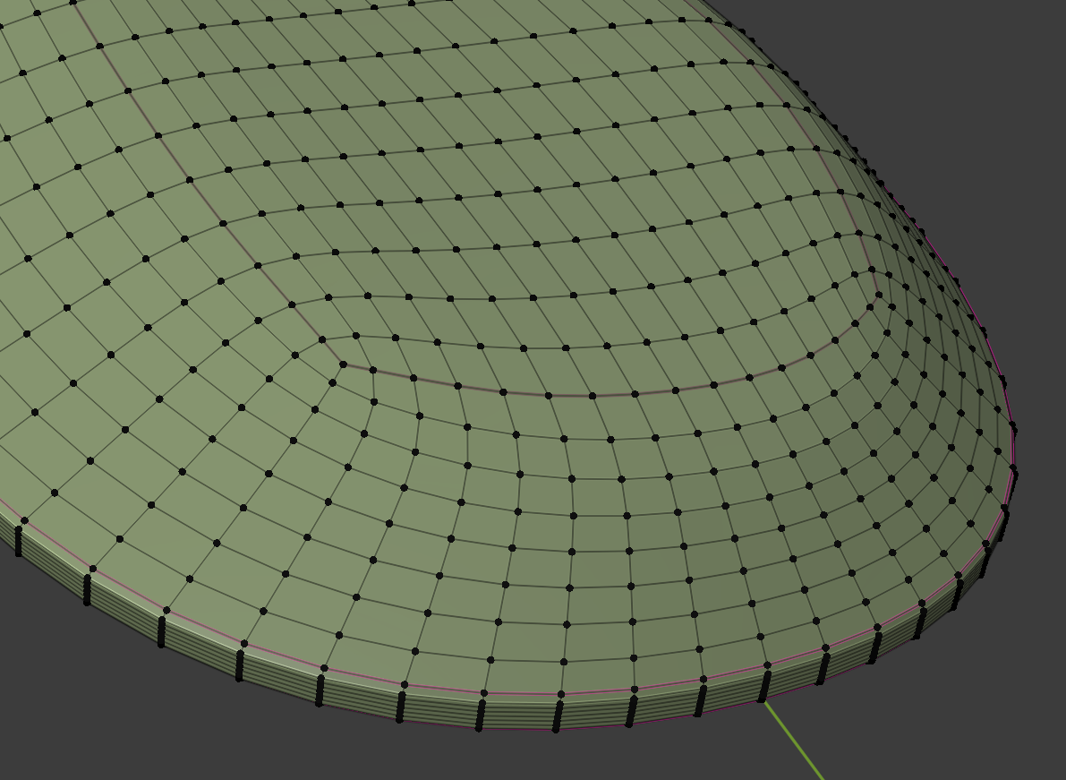
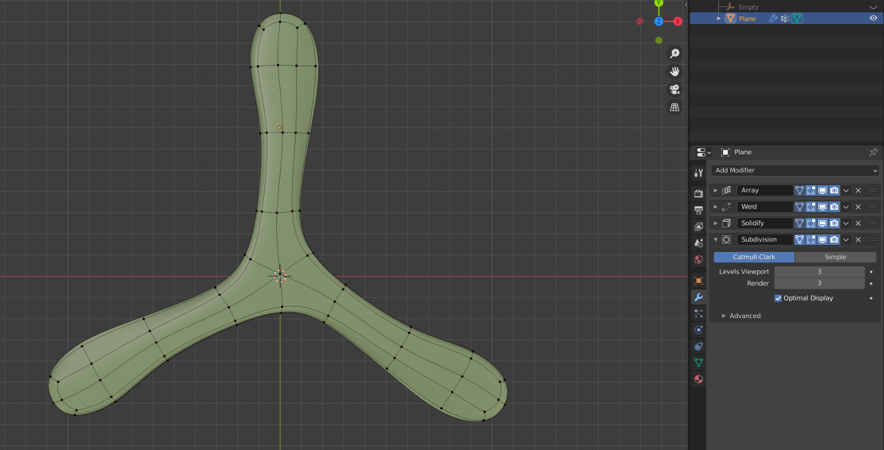
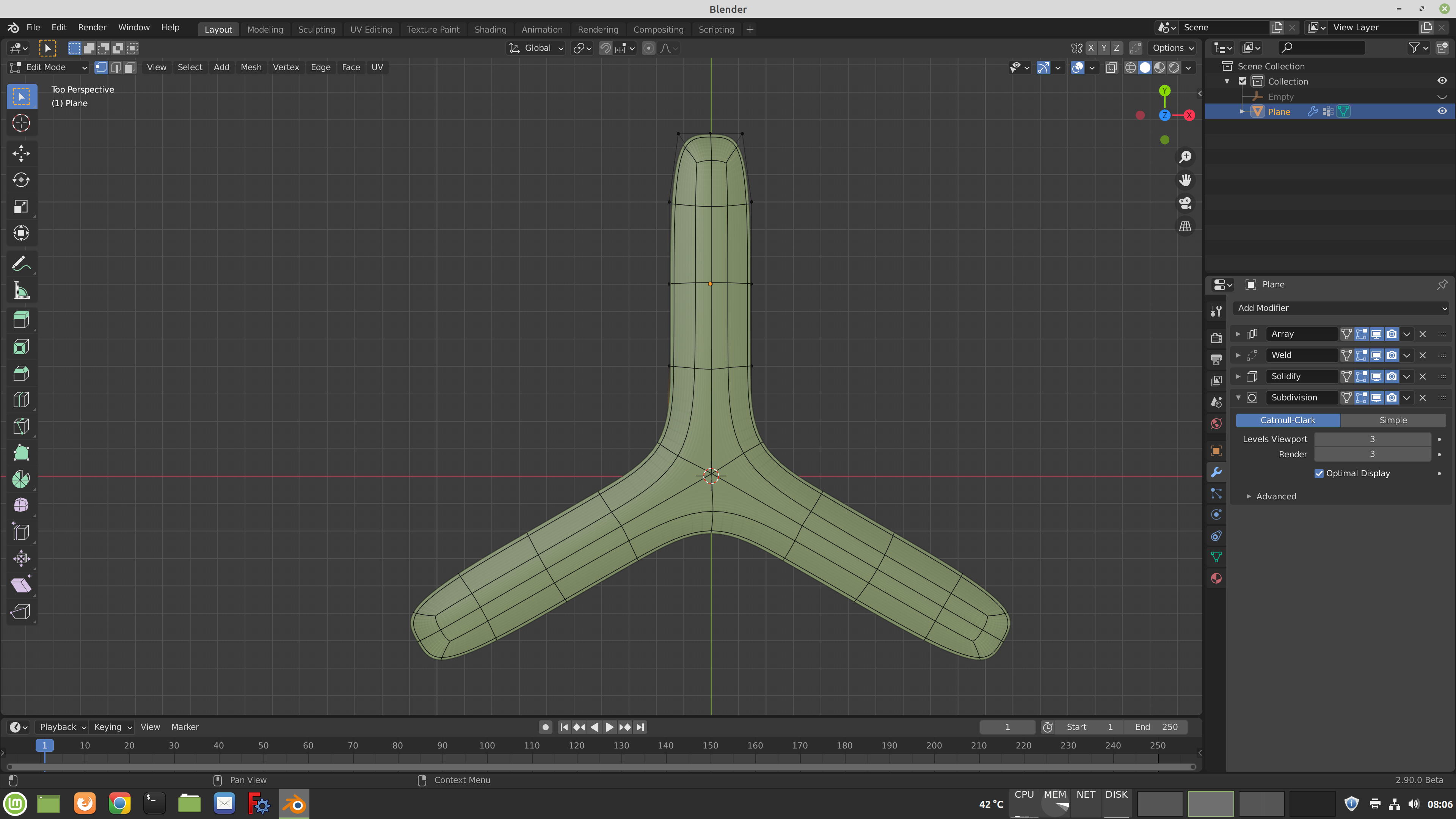
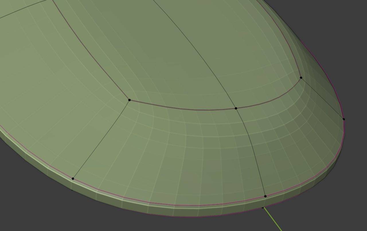
So far, our boomerang looks pretty rough. We can smooth it out using a Subdivision Surface modifier.

The modifiers support an "On Cage" setting. That allows us to see the original geometry in edit mode in the shape that it will be after applying the modifiers. This makes it much easier to see what we are doing.
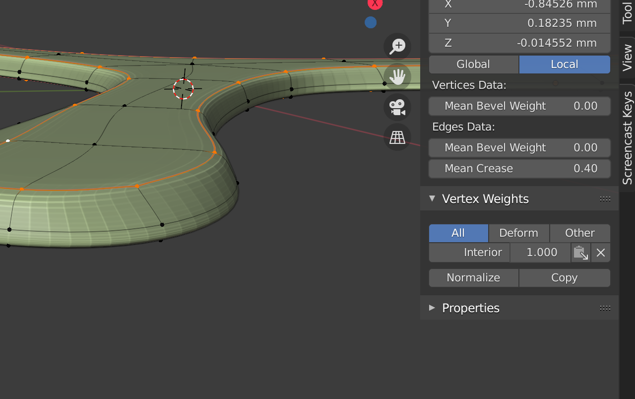
I like my boomerang shapes to be a little more defined so they print more cleanly. To achieve that, mark the edge loops (Shift-Alt-Click) that should be less rounded, and set the "Mean Crease" amount in the Properties panel (N).

This is the time to make some final adjustments to our geometry. If everything works as intended, we should be able to move around one vertex of the original geometry, and all three wings should update accordingly. Be sure to move vertices only in the XY plane (G Shift-Z or GG) – it's too easy to accidentally move them in the Z direction and end up with a bumpy shape.
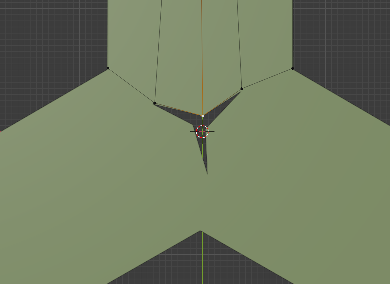
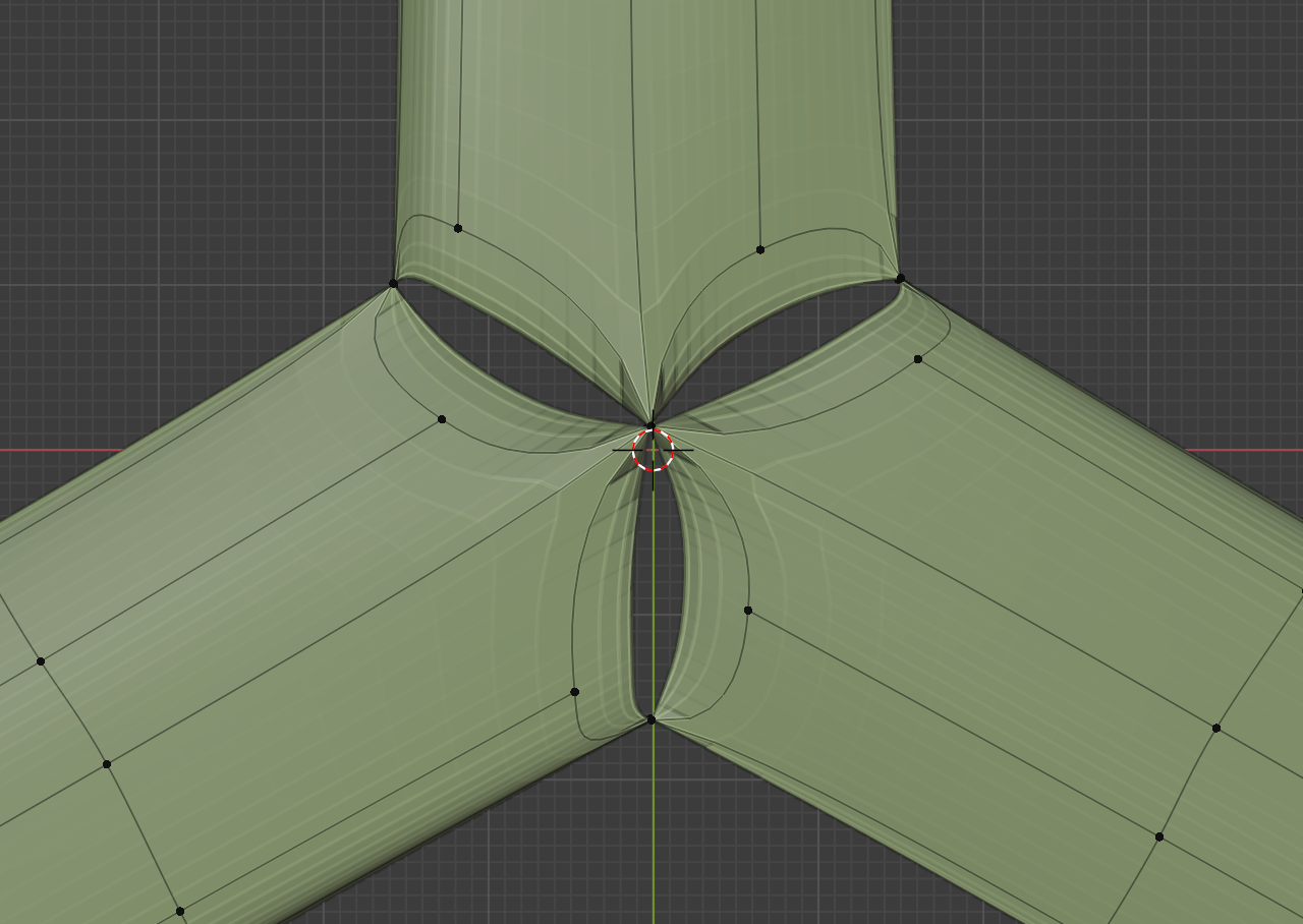
Take care when moving around the vertices from the weld group. The center of the boomerang could fall apart like this when moving those around. Don't panic – just move the opposite vertex to the same spot so that the center region welds back together. That can be easier if the subsurf modifier is turned off.
When exporting the boomerang to STL for printing, make sure to check the "Only Selection" and"Apply Modifiers" boxes, and set the scale to 1000 – otherwise the export will be way too small and your slicer may behave funnily.
Final Result
Here's a comparison of the editable geometry in our non-destructive approach: it consists of 26 vertices, 43 edges and 18 faces, all of which we can easily manipulate.
If I apply the subsurf modifier to level 4, we end up with 35,000 vertices, 70,000 edges and 35,000 faces. That's the geometry that we end up 3D printing, but I certainly wouldn't want to have to make changes to that.