Introduction
In this article, we will create a parametric boomerang model in CAD. Parametric means that we will be able to change aspects of our model after the fact, such as changing dimensions or angles.
We will be able to say: make that angle a bit tighter, or make that wing a little longer, and the finished model will update accordingly. The way this works is that the different parts of the boomerang, such as lines, arcs, and faces, are specified in relationship to each other: this line is perpendicular to that one, this arc flows into that line, etc.
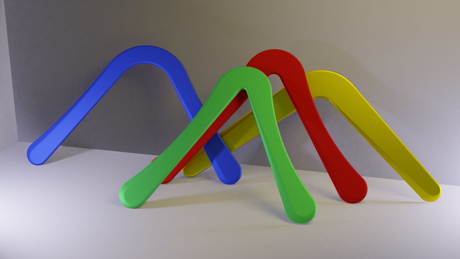
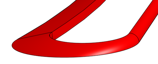
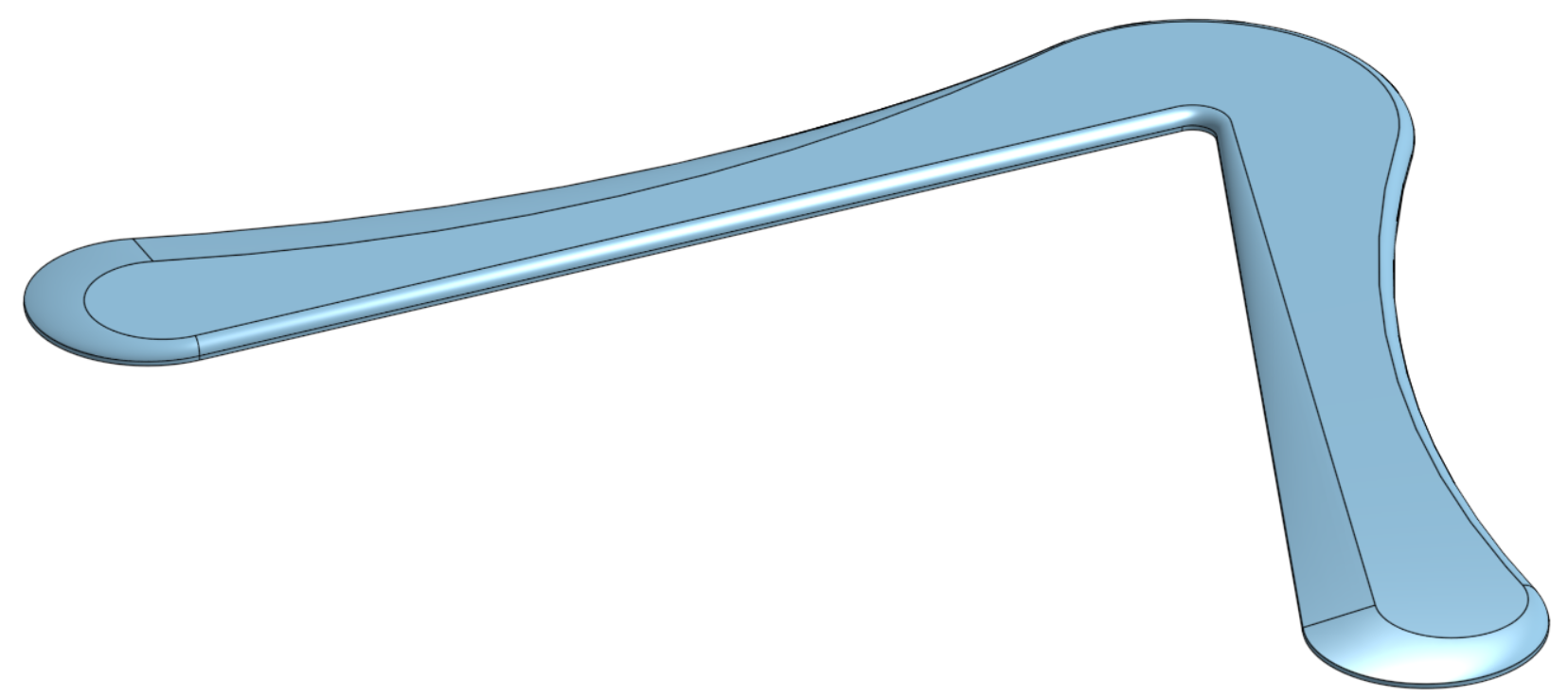
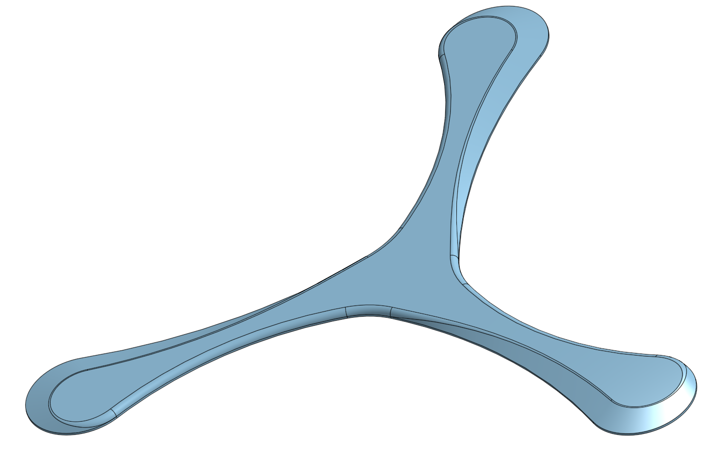
This will allow you to create an infinite number of variations of a basic boomerang shape. Someone with their own 3D printer, for example, will be able to very easily experiment with different boomerang shapes. The boomerangs in this picture, for example, were all created from the same CAD model just by changing parameters.
Note: the examples in this document are available here.
Software
I will use Onshape for this article. Other CAD programs such as Fusion 360, SolidWorks, or Creo will work just the same. The only requirement is that the CAD program will have to support so-called lofting, which basically means that it can create surfaces by stretching a sort of rubber skin over two or more outlines, just like this:

To create this, I drew the top and bottom outlines and then had the CAD program create the surfaces between those.
It is also possible to make a boomerang with more of a free-form modeling approach, instead of using parametric CAD. I covered that in a companion article on this site, using Blender.
Modeling Approaches
There are two distinguishing features of a boomerang which need to be modeled:
- the outline, i.e. the shape of the boomerang if you traced around it on a piece of paper
- the airfoil, i.e. the cross section of the wings that the air streams over
The difficulty is that the airfoil changes along the wings, so that there are no two points on the boomerang that have exactly the same cross section.
In this article, I will show three different approaches for creating a boomerang-shaped CAD model:
Lofting the Outline:
 We model the outlines of the boomerang's top and bottom (as seen lying flat on a table). The space in between is filled in with a loft. This is definitely the easiest way of constructing a workable boomerang.
Sweeping the Airfoil:
 We start with the cross-section of the wings at different points and sweep the cross-section along the length of the wings. I think this approach is the most intuitive one, as it mimics the way we make boomerangs by hand. It is kind of difficult, though, to create the tips of the wings this way.
Sweeping Half-Airfoils:
 We model the leading and trailing edges of the wings at different points, and interpolate between those shapes along the outline of the boomerang. This is similar to the previous approach, but it is a little more tedious since we have to manage more different shapes.
I found it to be more predictable regarding the resulting shape, though.
We model the leading and trailing edges of the wings at different points, and interpolate between those shapes along the outline of the boomerang. This is similar to the previous approach, but it is a little more tedious since we have to manage more different shapes.
I found it to be more predictable regarding the resulting shape, though.
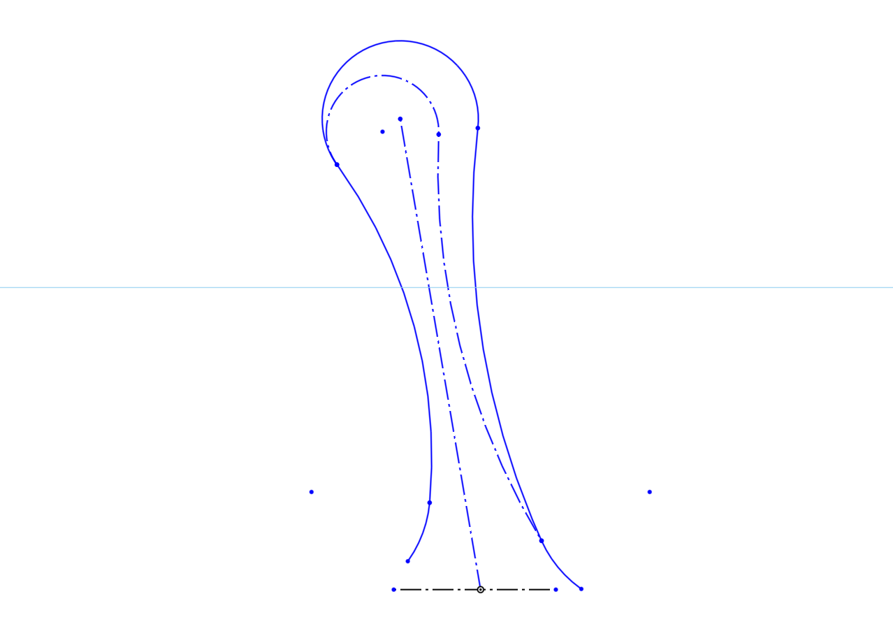
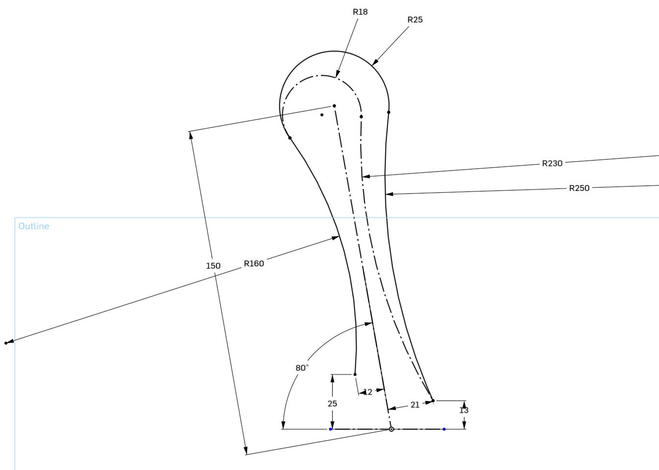
The Basics: Sketching the Boomerang's Outline
Onshape Document: Misc → Sketching Basics
For all of the three approaches, we need to draw the outline of our boomerang. In CAD, such a 2D drawing that aids 3D construction is called a sketch.
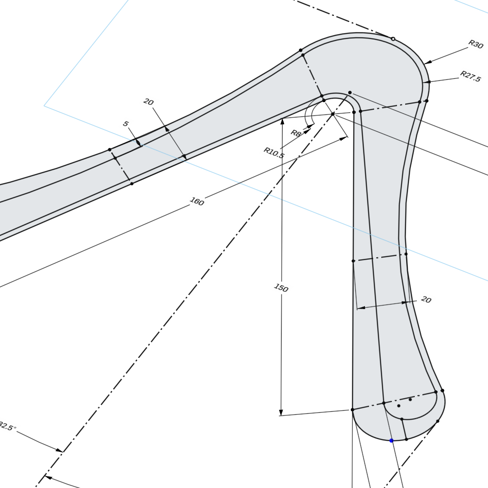
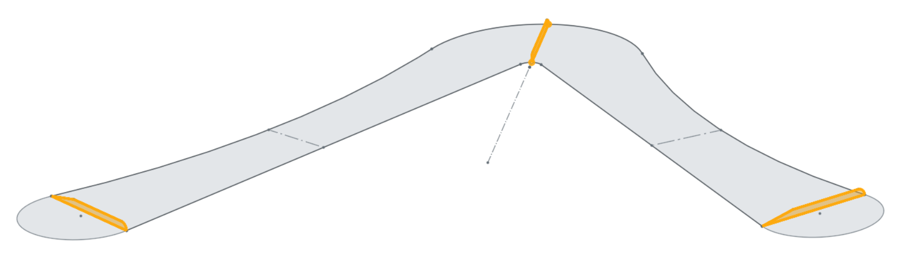
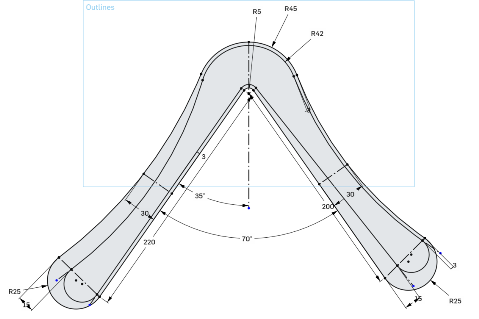
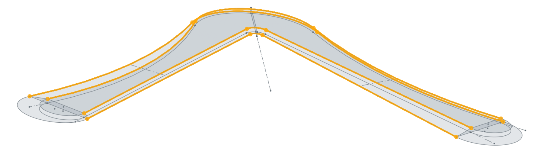
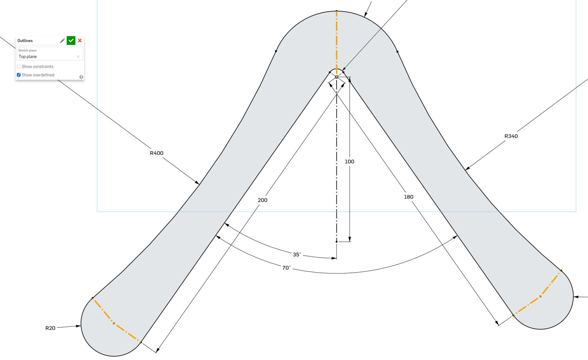
For the boomerang model shown here, that sketch consists of eight shapes:
- The elbow consists of two concentric arcs, i.e. parts of circles.
- The wingtips consist of one arc each.
- Each wing consists of a straight line on the inside and an arc on the outside.
I would usually construct these so that they are connected in the first place. Here they are displayed separately for clarity:

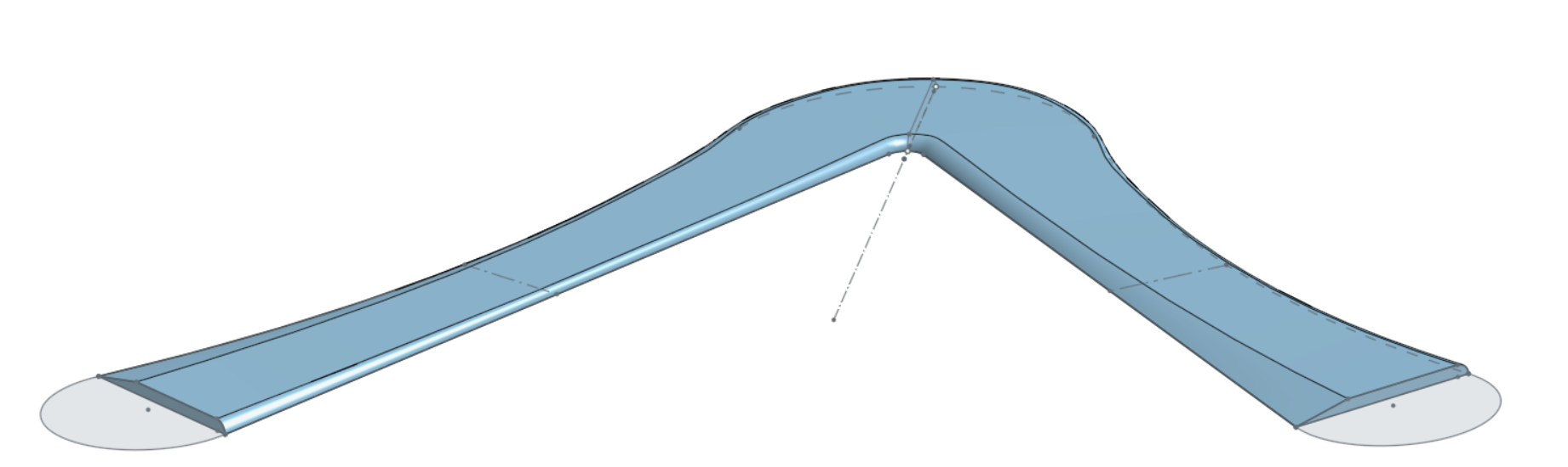
In order to join all of these rough shapes together in a way that makes sense, we will constrain them. Constraining means to state conditions that the shapes have to fulfill, such as specific measurements (called dimensions in CAD language), or relationships to each other. Those relationships could be two elements meeting at a point, or a curve being tangent to a line, two lines being perpendicular, etc.
We need to specify just the right number of constraints. If we have too few constraints, the CAD system will not be able to figure out unambiguous positions for everything. If we have too many constraints, they can contradict each other.
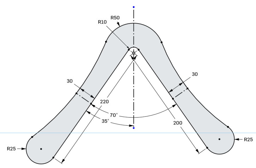
In the outline drawing above, we'll add the following constraints:
- the endpoints of adjacent lines are coincident with one another
- wherever lines meet, make them tangent so each line flows into the next one
- dimensions are added for the lengths of the wings
- dimensions are added for radii of the elbow arcs and the wing tips
- we specify the widths of the wings at their midpoints; to do that we add
construction lines perpendicular to the midpoints of each wing so we have something to attach the dimension - we state the elbow angle, and tie that to a vertical construction line so our boomerang sketch stays upright (with the elbow on top)
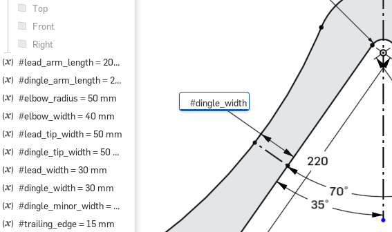
To make it easier to change all of those around later, I also add variables
for each of the dimensions so I can refer to them by name. The value can be
referred to anywhere you enter a dimension, such as #dingle_width in this example:
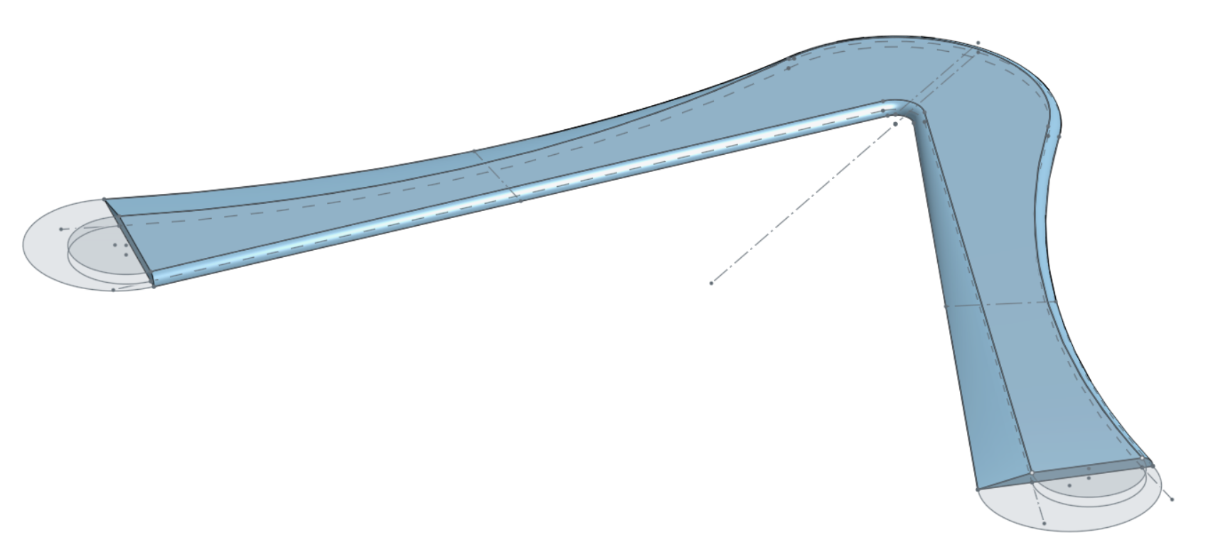
Fully constrained, the sketch will look like this:
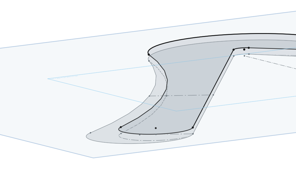
Approach 1: Lofting the Outline
Here's a video showing this approach:
Onshape Document: Loft Outline
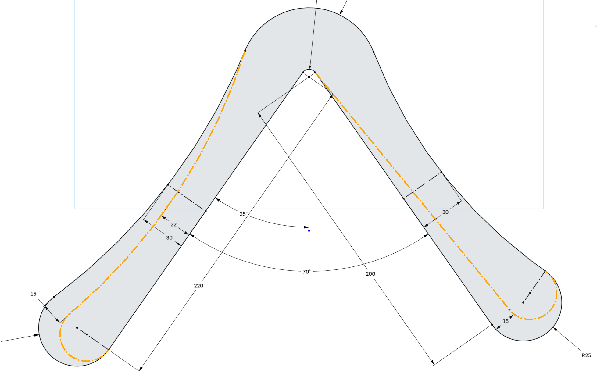 Using the outline we created above as a starting point, we need to sketch some more
geometry to create our trailing edges later on.
The highlighted construction lines mark our trailing edges. They consist of two arcs
near the wingtips, and an arc and a line, respectively, from the elbow tangentially to the arcs near the wingtips.
Using the outline we created above as a starting point, we need to sketch some more
geometry to create our trailing edges later on.
The highlighted construction lines mark our trailing edges. They consist of two arcs
near the wingtips, and an arc and a line, respectively, from the elbow tangentially to the arcs near the wingtips.
 We now want to create the top side of our boomerang.
We create an offset plane above our sketch, make a new sketch,
and use (project) the trailing edge outline onto it. It is easier to sketch the
trailing edges along with the outline in the bottom sketch, so we take this approach of projecting them to the top plane instead of sketching them separately.
We now want to create the top side of our boomerang.
We create an offset plane above our sketch, make a new sketch,
and use (project) the trailing edge outline onto it. It is easier to sketch the
trailing edges along with the outline in the bottom sketch, so we take this approach of projecting them to the top plane instead of sketching them separately.
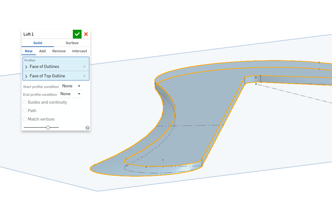 Now we can loft between our bottom and top sketches. No further options or
construction geometry are needed here. Just use the loft tool and pick the bottom and top outlines.
Now we can loft between our bottom and top sketches. No further options or
construction geometry are needed here. Just use the loft tool and pick the bottom and top outlines.
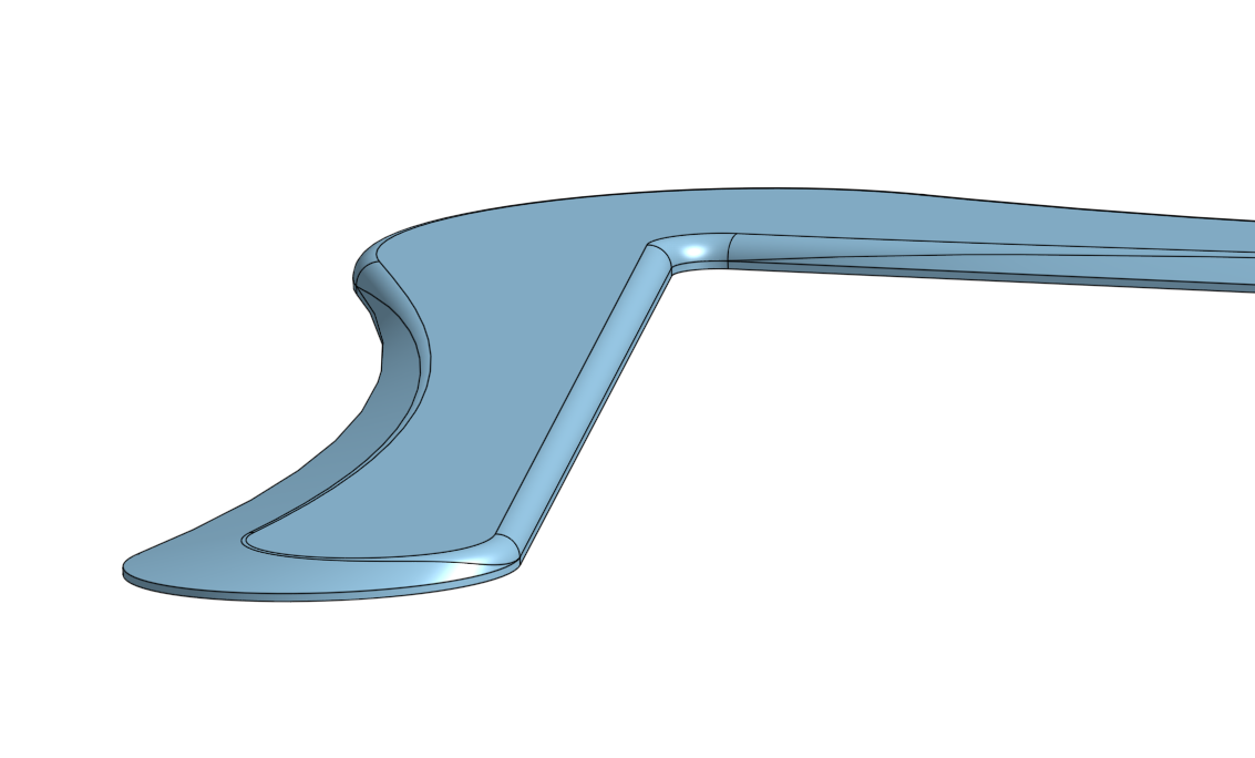 To finish our boomerang, I add a fillet to the top outline to round over all the edges, the leading edges in particular. I also extrude the bottom sketch 1 mm downwards so our airfoils don't end up too pointy.
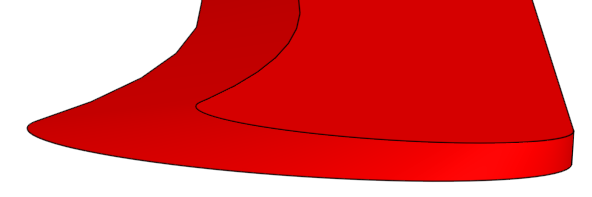
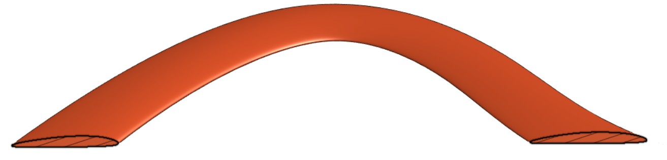
The obvious drawback of this approach is the lack of control over the exact shape of the airfoils. We are basically limited to a beveled trailing edge and a fillet for the leading edge.
Approach 2: Sweeping the Airfoil
Onshape Document: Sweep Full Airfoil
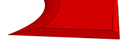
This approach will allow us much more fine-grained control over the airfoils.
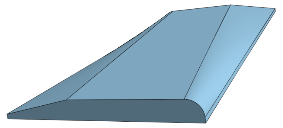 If you think about your boomerang as a stick bent into a U or V shape and bend
that stick straight, what remains is a board with an airfoil which gradually changes
its direction along its length like this. We will do the same thing along the shape
of our boomerang as defined by the outline we drew before.
If you think about your boomerang as a stick bent into a U or V shape and bend
that stick straight, what remains is a board with an airfoil which gradually changes
its direction along its length like this. We will do the same thing along the shape
of our boomerang as defined by the outline we drew before.
Sweeping the Airfoil: The Simple Way
I will first show the general idea, but unfortunately, the simple version fails. We will be able to repair that, but it takes a little more work.
 We start with an outline of our boomerang and draw construction lines across the width of the wings where we want to add
airfoil sketches later.
We start with an outline of our boomerang and draw construction lines across the width of the wings where we want to add
airfoil sketches later.
 Here is the main idea: on the construction lines we made before, we create some sketch planes (select the line, Plane → Line Angle).
On each of those planes, we sketch the airfoil we want at that position.
Here is the main idea: on the construction lines we made before, we create some sketch planes (select the line, Plane → Line Angle).
On each of those planes, we sketch the airfoil we want at that position.
 We can now loft the airfoils between our sketches, using the outline as guides.
 Unfortunately, this does not work out as intended – the wings sort of sink in between the sketches, as can be seen in the picture.
Perspective was turned off, so what we see here is really uneven thickness of the wings and not some sort of artifact of the
3D view. It almost seems as if the material was "stretched thin" between our airfoil sketches.
Unfortunately, this does not work out as intended – the wings sort of sink in between the sketches, as can be seen in the picture.
Perspective was turned off, so what we see here is really uneven thickness of the wings and not some sort of artifact of the
3D view. It almost seems as if the material was "stretched thin" between our airfoil sketches.
Sweeping the Airfoil: The Correct Way
 We can fix the thickness issue by adding some more construction geometry to guide our lofts. In this outline sketch, note I added
an inner outline (oxymoron warning!), almost as in the previous approach, but all the way around (and not just for the trailing edges).
We can fix the thickness issue by adding some more construction geometry to guide our lofts. In this outline sketch, note I added
an inner outline (oxymoron warning!), almost as in the previous approach, but all the way around (and not just for the trailing edges).
 We can now create an offset plane above our outline sketch, and pull in the geometry for the inner outline using the Use/Project feature.
 Now the airfoil sketches can be created as before, making sure that they coincide with the additional geometry we just created on
the top plane.
Now the airfoil sketches can be created as before, making sure that they coincide with the additional geometry we just created on
the top plane.
 Before we can create the main body of the boomerang, we create some Composite Curves as guides. These are curves created from
three separate lines each which we select from our outlines. Perhaps we could get away without those, but having these curves makes
managing the lofting process easier.
Before we can create the main body of the boomerang, we create some Composite Curves as guides. These are curves created from
three separate lines each which we select from our outlines. Perhaps we could get away without those, but having these curves makes
managing the lofting process easier.
 We can now loft the main airfoil between our three sketches, using one of the composite curves as a Path and all four of them as Guides.
The thickness issue from above is now fixed thanks to the additional guides on the top plane.
We can now loft the main airfoil between our three sketches, using one of the composite curves as a Path and all four of them as Guides.
The thickness issue from above is now fixed thanks to the additional guides on the top plane.
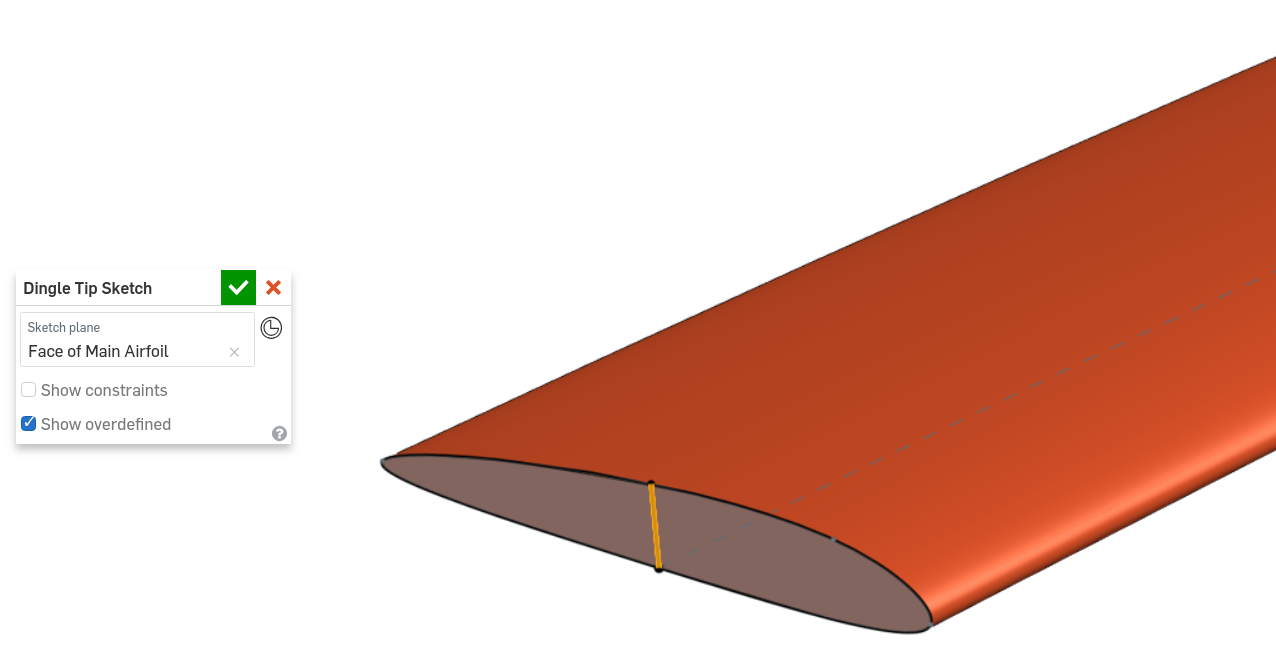
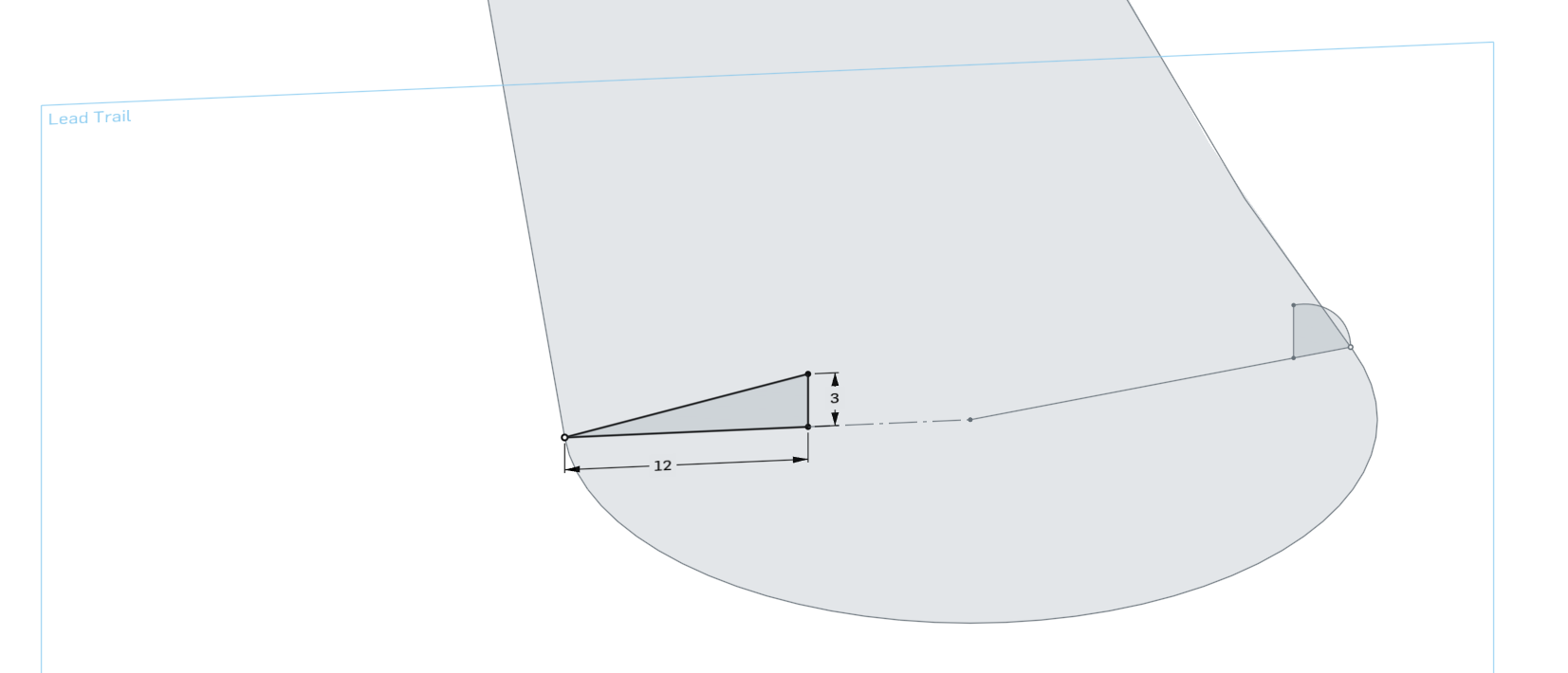
 The last thing to do is to create wingtips. To do that, I add a sketch on the end of the main body and add two vertical lines to part off
a leading and trailing edge of the airfoil.
The last thing to do is to create wingtips. To do that, I add a sketch on the end of the main body and add two vertical lines to part off
a leading and trailing edge of the airfoil.
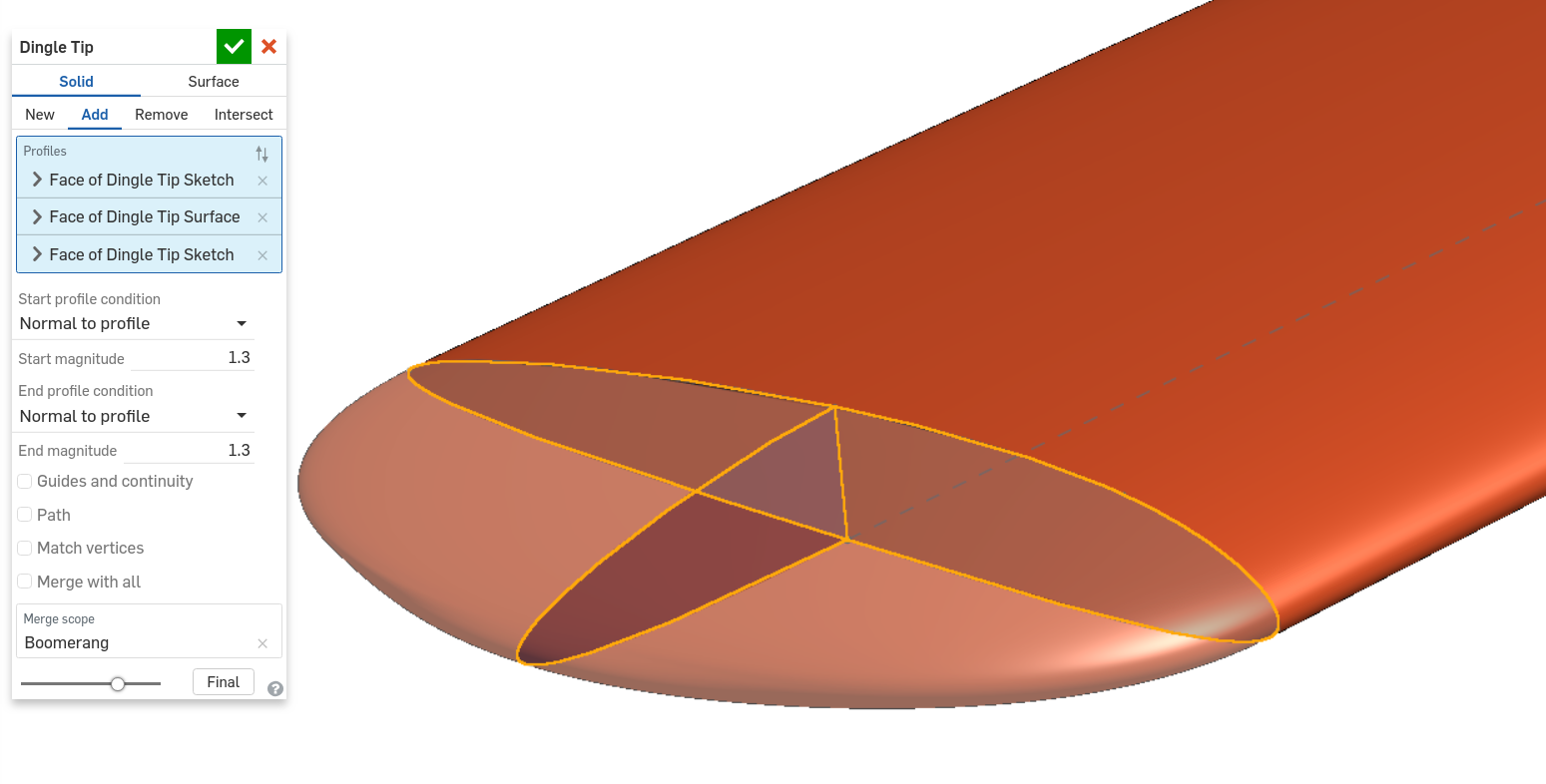
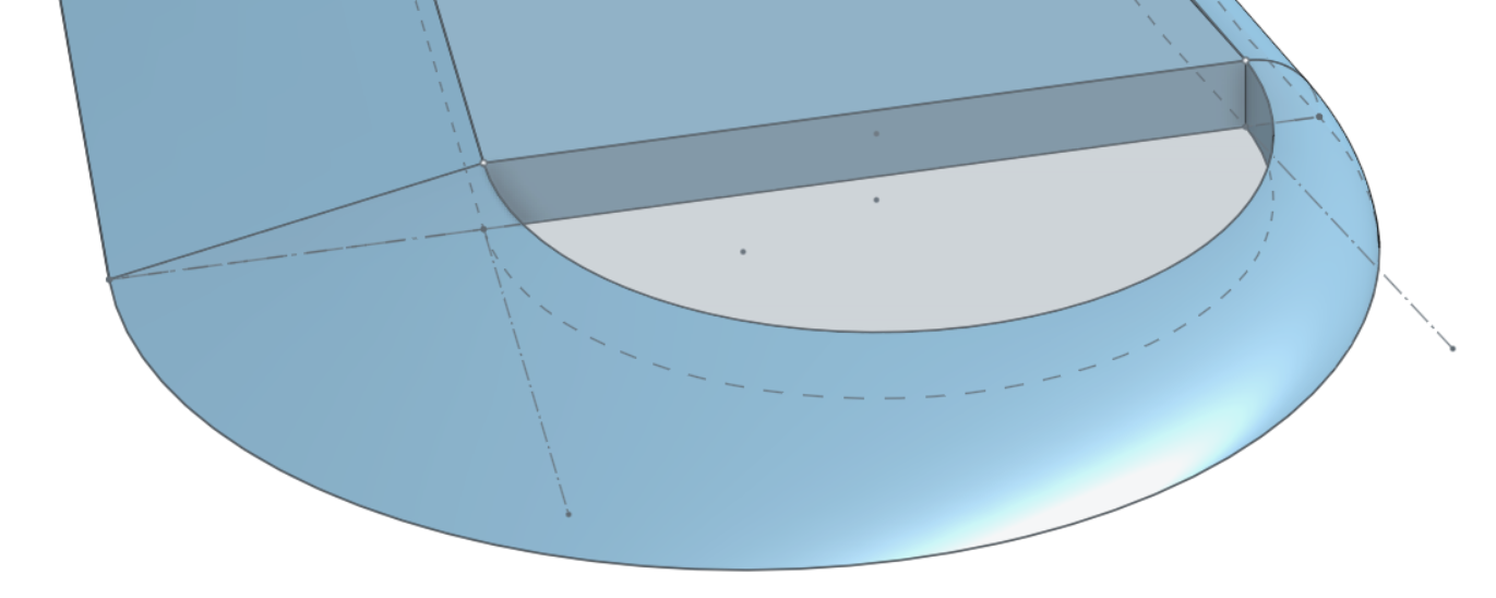 The wingtip is created by lofting the leading into the trailing edge, using the already existing geometry as a path and as guides.
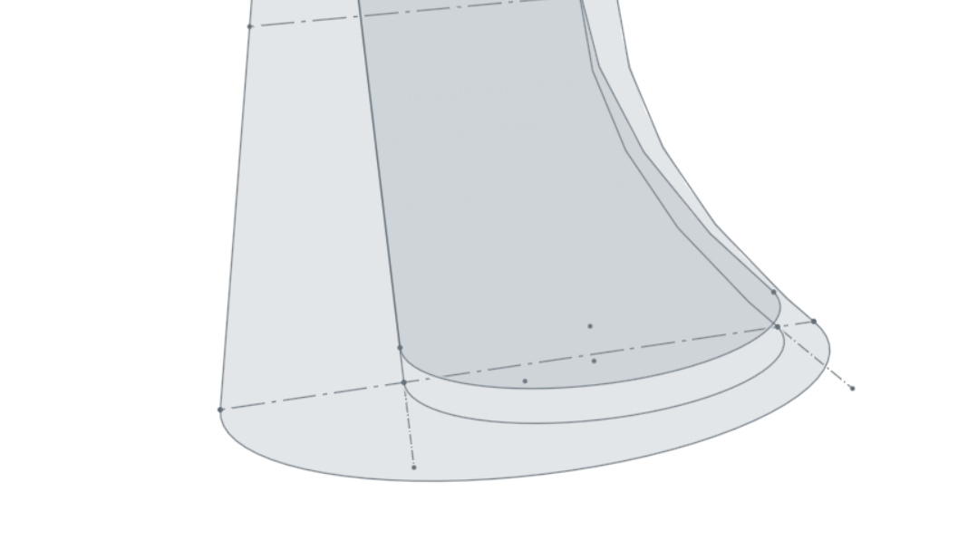
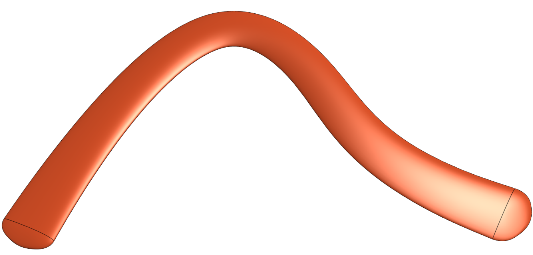
 The finished boomerang. To fill in the gaps at the wingtips, I used the "inner outline" that was already there and extruded it to the full
thickness of the boomerang. Also, I extruded the whole outline at the bottom a little way downwards to reduce the pointiness of the airfoils.
We could have sketched that directly into the airfoils, of course, but this is quicker.
The finished boomerang. To fill in the gaps at the wingtips, I used the "inner outline" that was already there and extruded it to the full
thickness of the boomerang. Also, I extruded the whole outline at the bottom a little way downwards to reduce the pointiness of the airfoils.
We could have sketched that directly into the airfoils, of course, but this is quicker.
Organic shapes
Onshape Document: Sweep Full Airfoil → Splines All Around
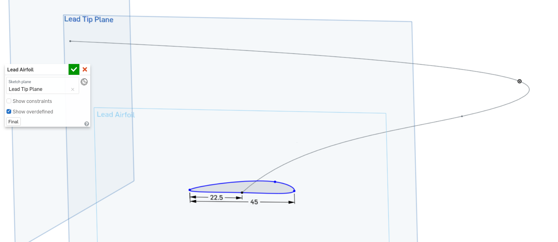
So far our boomerang shapes and airfoils have been based on the relatively simple geometry of straight lines and arcs. With the airfoil sweeping technique, though, it is also possible to create organic shapes based on freeform curves (so-called splines).
 In this example, I have decided to create a hook-shaped boomerang not from a full
outline, but from a center line. Let's call this the backbone of this boomerang. The backbone is a spline. It can be controlled by placing
a number of control points onto our sketch plane. At the ends, the curvature of the splines can also be controlled using handles.
In this example, I have decided to create a hook-shaped boomerang not from a full
outline, but from a center line. Let's call this the backbone of this boomerang. The backbone is a spline. It can be controlled by placing
a number of control points onto our sketch plane. At the ends, the curvature of the splines can also be controlled using handles.
 As before, I construct airfoils at certain points along the backbone. These, too,
are made from splines – for the airfoils, we use closed loops, though. To avoid unpleasant surprises later, I tie the airfoils to the backbone
by constraining one spline point to be coincident with the backbone.
As before, I construct airfoils at certain points along the backbone. These, too,
are made from splines – for the airfoils, we use closed loops, though. To avoid unpleasant surprises later, I tie the airfoils to the backbone
by constraining one spline point to be coincident with the backbone.
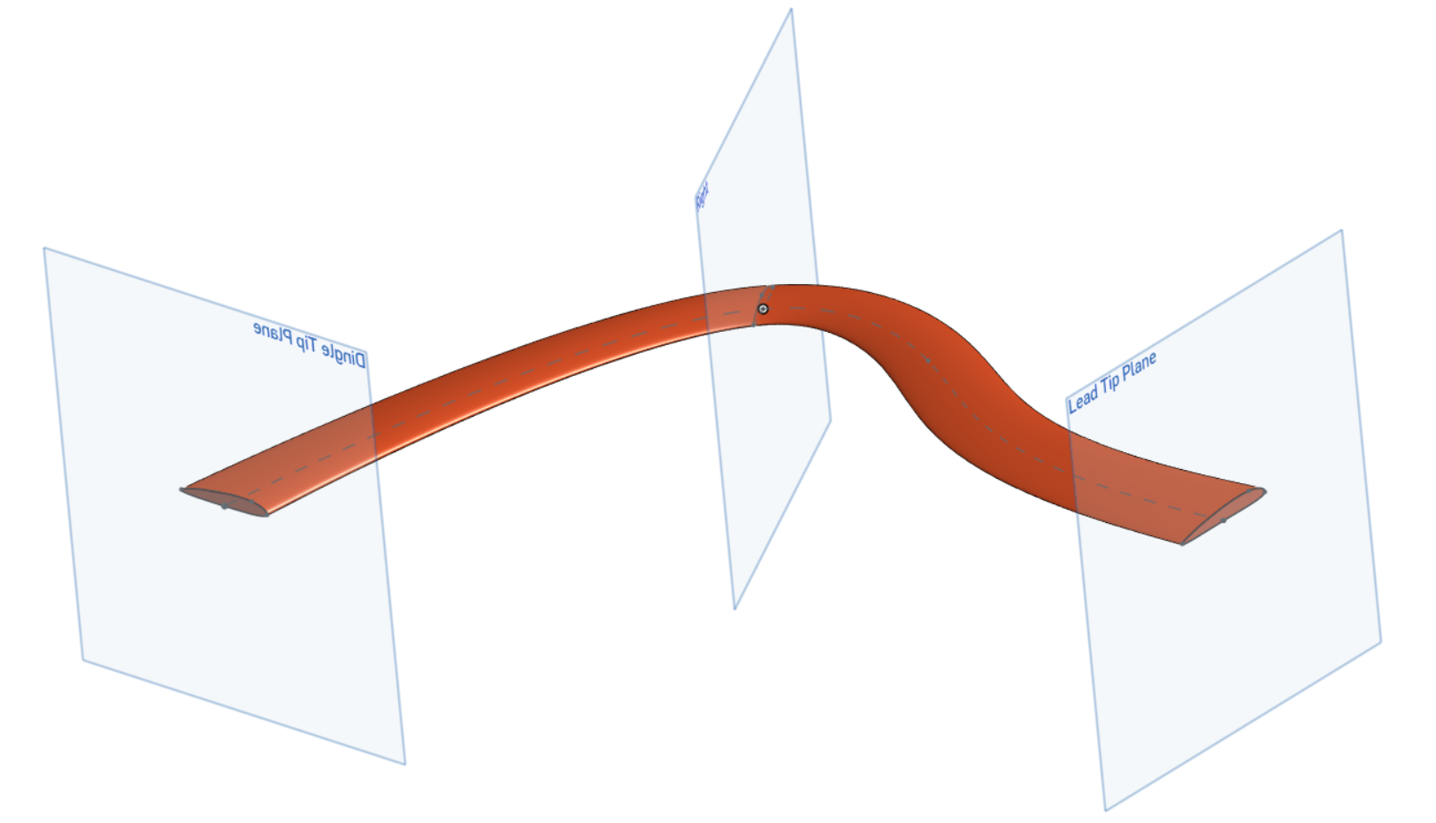 We can now loft the airfoils into each other, using the backbone as the path.
 Creating the wing tips is a little tricky this time. First, I want to construct
the cross section of the wingtip. To be able to do that, I create a sketch on the flat end of each wing tip and construct a vertical line that intersects
with the backbone (use the Use/Project feature to grab the endpoint of the backbone).
Creating the wing tips is a little tricky this time. First, I want to construct
the cross section of the wingtip. To be able to do that, I create a sketch on the flat end of each wing tip and construct a vertical line that intersects
with the backbone (use the Use/Project feature to grab the endpoint of the backbone).
 On the endpoints of the vertical line, I can now create a 3D Fit Spline. For the
direction of the spline, I use the backbone. With the start and end magnitudes, I can control how far the wingtip will stick out at the top and bottom sides. If necessary, I could also construct a sketch plane that lines up with the backbone,
and sketch the spline for the wingtip explicitly. That way, better control over the exact shape of the wingtip can be
achieved.
On the endpoints of the vertical line, I can now create a 3D Fit Spline. For the
direction of the spline, I use the backbone. With the start and end magnitudes, I can control how far the wingtip will stick out at the top and bottom sides. If necessary, I could also construct a sketch plane that lines up with the backbone,
and sketch the spline for the wingtip explicitly. That way, better control over the exact shape of the wingtip can be
achieved.
 With that curve in place, I can turn it into a surface with the Fill tool. Now we have
everything in place to create our wingtip with the Loft tool. We select both halves of our airfoil as well as the curve we just created for the loft.
For the end conditions, we use Normal to Profile since we want the wingtip to flow into the rest of the wing. With the start and end magnitudes,
we can control the exact shape of the wingtip.
With that curve in place, I can turn it into a surface with the Fill tool. Now we have
everything in place to create our wingtip with the Loft tool. We select both halves of our airfoil as well as the curve we just created for the loft.
For the end conditions, we use Normal to Profile since we want the wingtip to flow into the rest of the wing. With the start and end magnitudes,
we can control the exact shape of the wingtip.
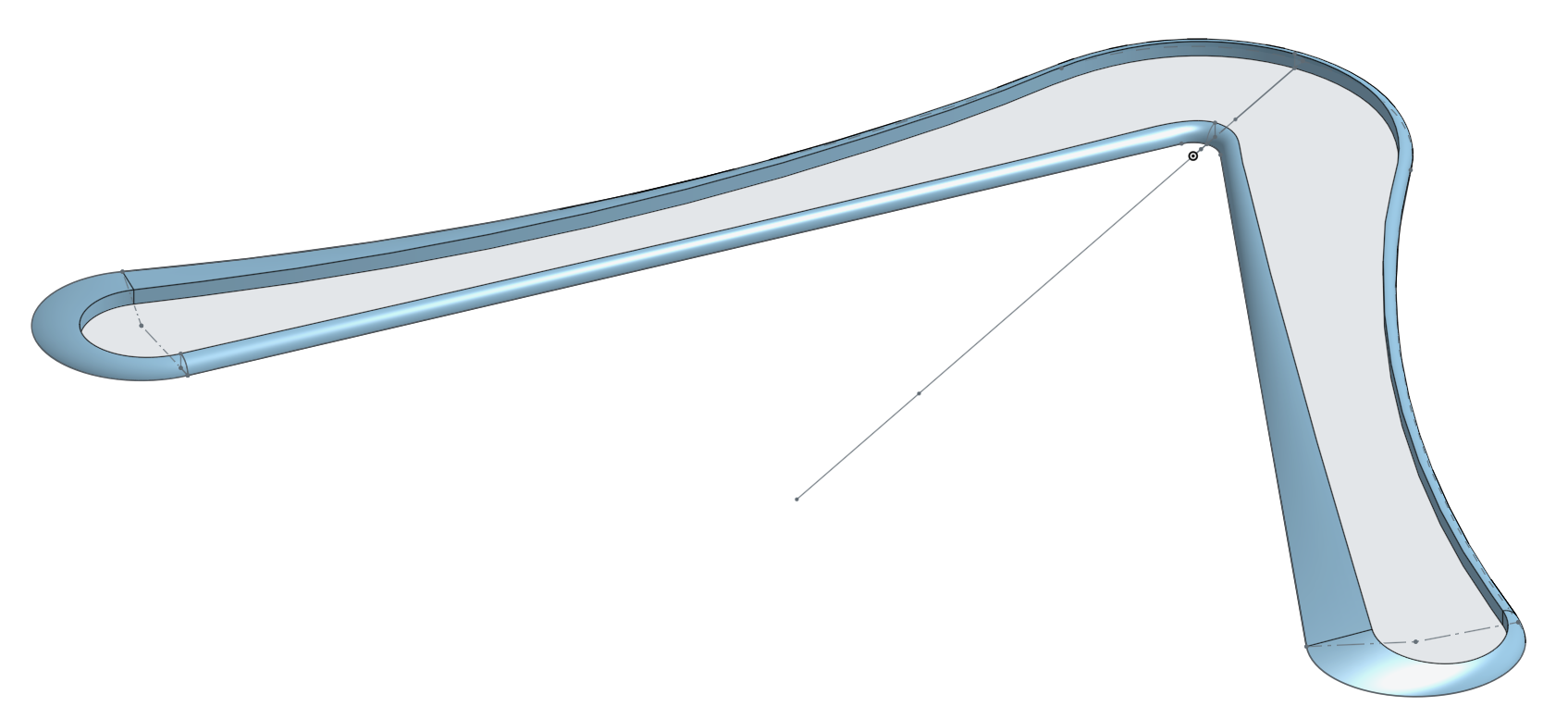
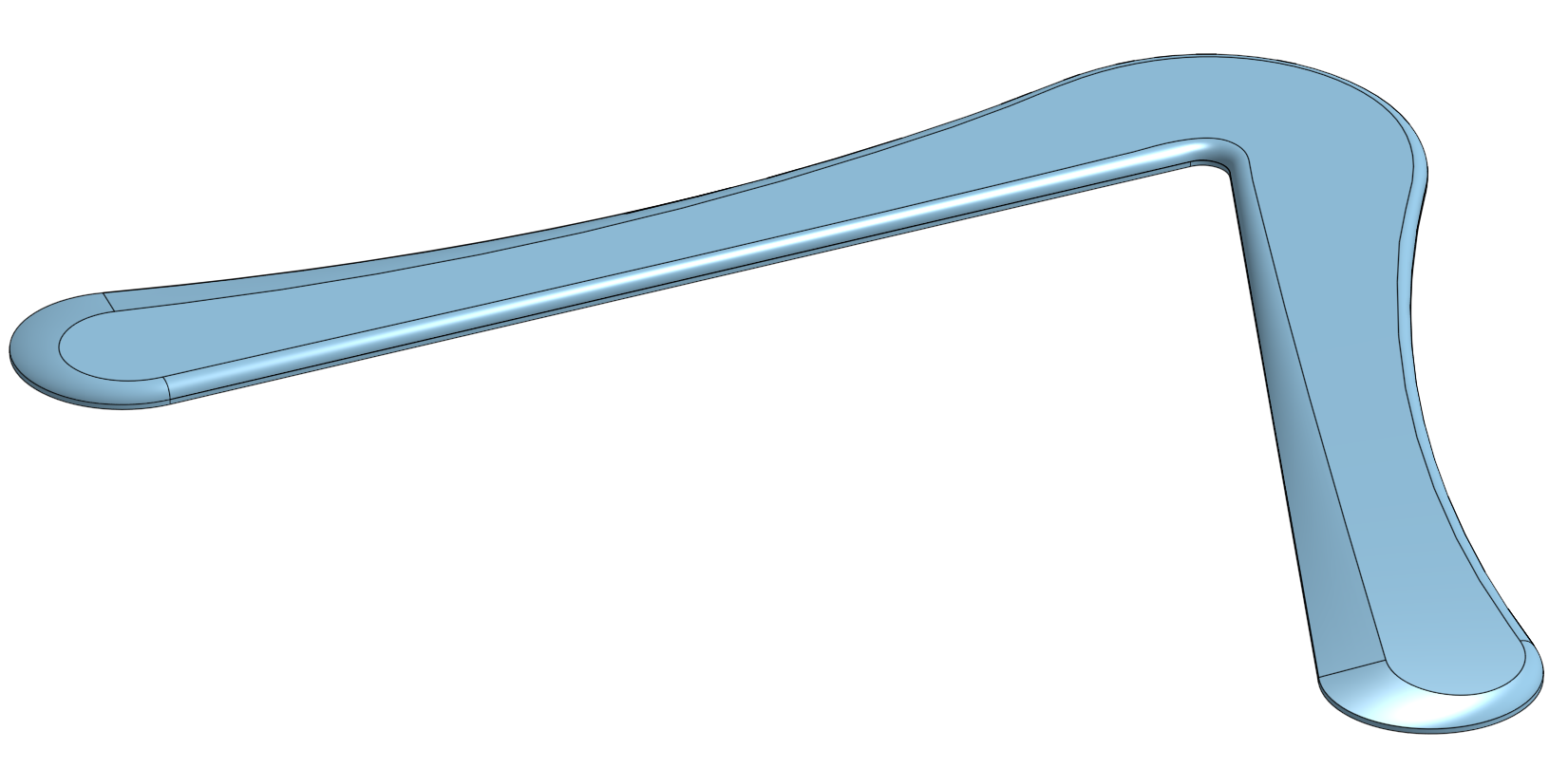
 This is what the finished boomerang looks like. As before, we can manipulate
all aspects of it – the backbone, the airfoils, and the wingtips – after the fact and the model will update accordingly. It is also possible to constrain
all of the splines we used with dimensioned construction geometry, so we could also use variables and configurations to more easily create variations.
This is what the finished boomerang looks like. As before, we can manipulate
all aspects of it – the backbone, the airfoils, and the wingtips – after the fact and the model will update accordingly. It is also possible to constrain
all of the splines we used with dimensioned construction geometry, so we could also use variables and configurations to more easily create variations.
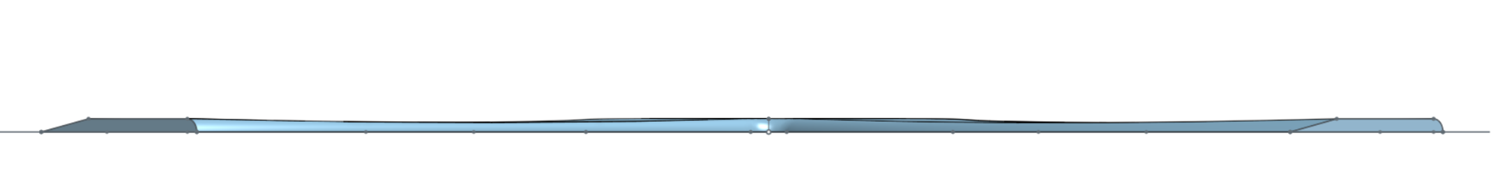
 The cross section view shows the nice organic shapes of the airfoils.
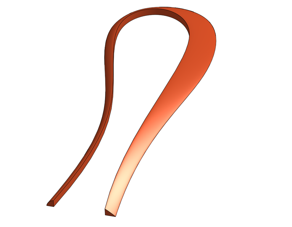
Approach 3: Sweeping Half-Airfoils
Onshape Document: Sweep Half Airfoils
The idea of this approach is to use the same technique that we used before to patch up the wingtips with half-airfoils, but now we do it on the whole boomerang.
 As before, draw the outline and add construction lines
at those points where you want to draw airfoils.
As before, draw the outline and add construction lines
at those points where you want to draw airfoils.
 At each of those construction lines, erect a vertical plane as before and
sketch a leading or trailing edge, respectively.
At each of those construction lines, erect a vertical plane as before and
sketch a leading or trailing edge, respectively.
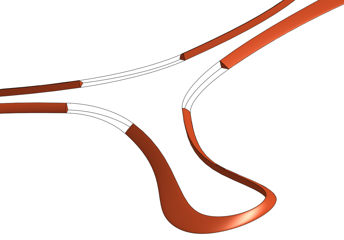
 Using the same techniques as before – creating composite curves, lofting with
paths and guides – we can now loft the inside and outside airfoils into each other.
Using the same techniques as before – creating composite curves, lofting with
paths and guides – we can now loft the inside and outside airfoils into each other.
 When we patch up the wing tips, we need to make
sure that we use the Add option of the loft and use the Merge with All merge scope
so we end up with one part instead of four separate ones.
When we patch up the wing tips, we need to make
sure that we use the Add option of the loft and use the Merge with All merge scope
so we end up with one part instead of four separate ones.
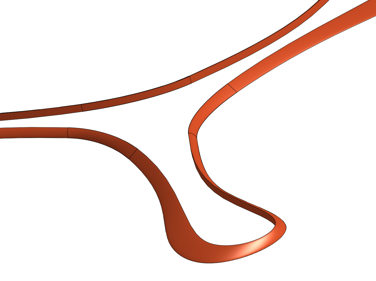
 To patch the inside, we create an extrusion
that fits right into the gap. Select the outline of the hole,
create a surface using the Fill tool, and extrude that to fill
the inside.
To patch the inside, we create an extrusion
that fits right into the gap. Select the outline of the hole,
create a surface using the Fill tool, and extrude that to fill
the inside.
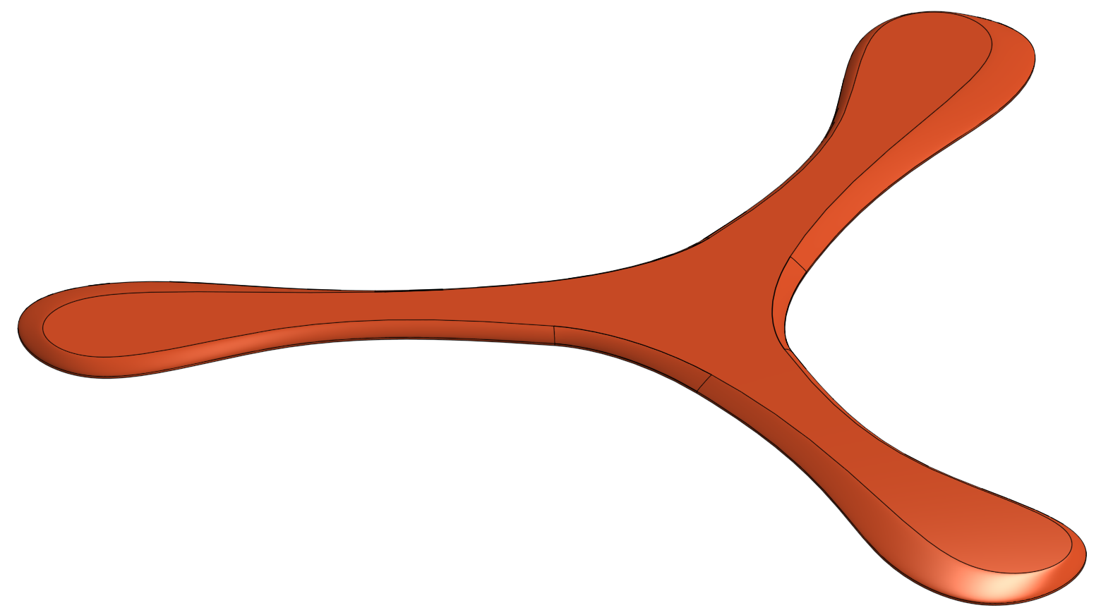
Modeling Tribladers
The idea when modeling tribladers, of course, is that those are usually symmetric, so we want to model a wing only once and then connect three copies of it. CAD systems such as Onshape have tools for creating symmetric patterns like that.
Depending of the modeling approach we choose, we can use the symmetry at different stages of our construction:
- For the outline loft approach, I would create a circular pattern of three wings at the sketch level and loft that outline as shown above.
- For the other two approaches, I would rather create the wing as a solid part and connect multiple copies it.
Tribladers From a Symmetric Outline
 In this approach, we use the symmetry of the boomerang
at the sketching level. I start with a sketch of one wing. In order to get a feeling for the final position of the wing – leaning forward a little is preferable
for a boomerang that is to fly low, such as a fast catch – I add a couple of straight construction
lines. The rest is just some arcs that are tangent to one another.
In this approach, we use the symmetry of the boomerang
at the sketching level. I start with a sketch of one wing. In order to get a feeling for the final position of the wing – leaning forward a little is preferable
for a boomerang that is to fly low, such as a fast catch – I add a couple of straight construction
lines. The rest is just some arcs that are tangent to one another.
 Fully constrained and dimensioned,
my sketch looks like this. Notice that everything is referenced off of the origin of our coordinate system and the horizontal construction line.
Fully constrained and dimensioned,
my sketch looks like this. Notice that everything is referenced off of the origin of our coordinate system and the horizontal construction line.
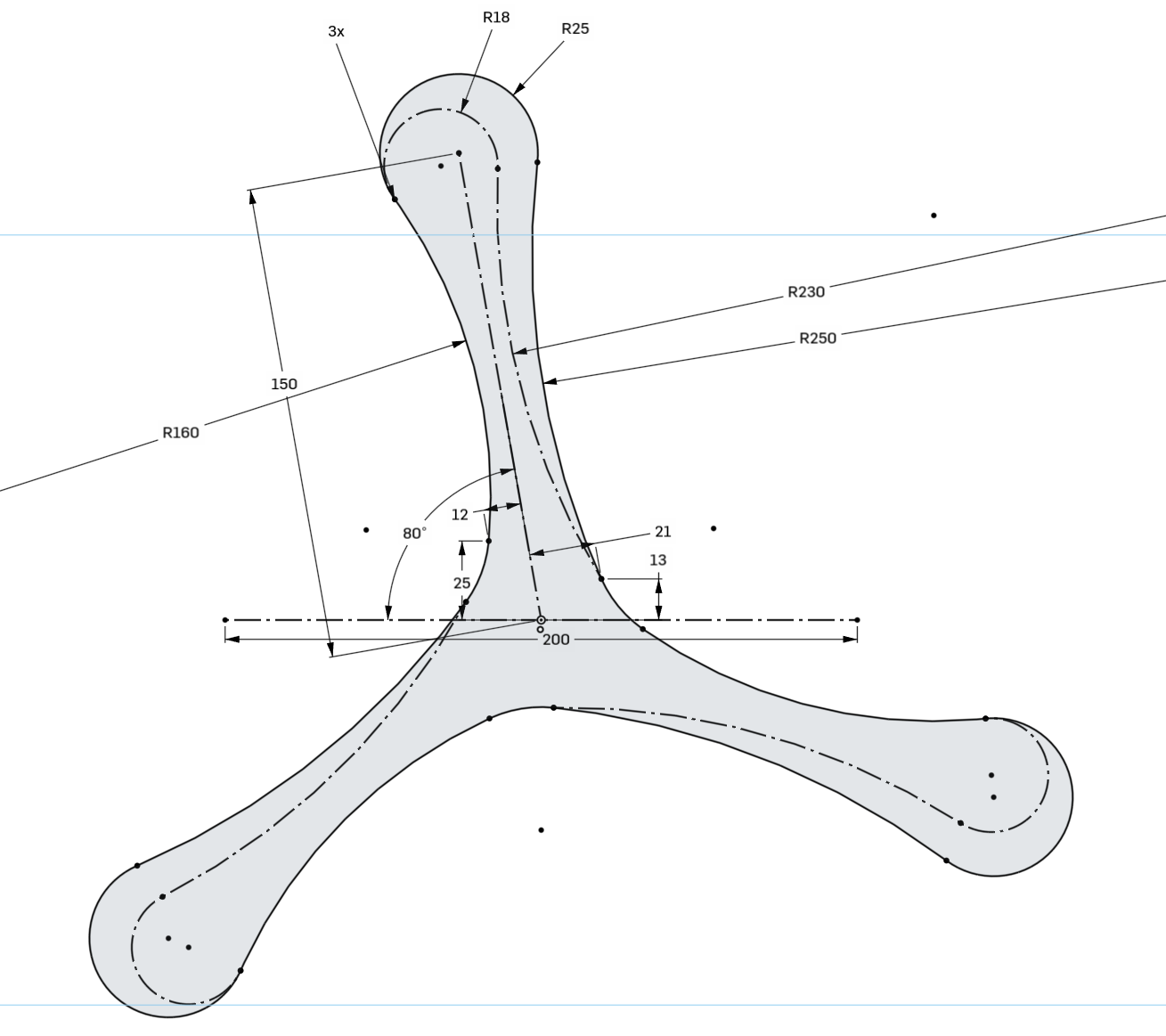 I can now create a circular pattern of three wings
in my sketch. There will be gaps between the wings – I patch those with some more tangent arcs.
I can now create a circular pattern of three wings
in my sketch. There will be gaps between the wings – I patch those with some more tangent arcs.
 The rest of the construction proceeds as
described above: create an offset plane; pull in the geometry from the sketch below using the "Use/Project" feature; create
the loft; round over the leading edges; add an extrusion to pad the bottom.
The rest of the construction proceeds as
described above: create an offset plane; pull in the geometry from the sketch below using the "Use/Project" feature; create
the loft; round over the leading edges; add an extrusion to pad the bottom.
Tribladers From a Circular Pattern of Wings
 Other than before, in this approach we first construct a solid body for
one wing. Copies of that wing will be arranged in a circular pattern and then patched into a closed form. I start off by sketching an outline for a wing and lofting half-airfoils
around it, as described in Approach 3 above. Approach 2 would work just the same.
Other than before, in this approach we first construct a solid body for
one wing. Copies of that wing will be arranged in a circular pattern and then patched into a closed form. I start off by sketching an outline for a wing and lofting half-airfoils
around it, as described in Approach 3 above. Approach 2 would work just the same.
 Now the wing can be arranged in a circular pattern. To do that,
we must first construct an axis perpendicular to our plane by sketching a construction line through the origin on one of the front or right planes.
Note that we use a circular pattern of solid bodies now, not a sketch pattern.
Now the wing can be arranged in a circular pattern. To do that,
we must first construct an axis perpendicular to our plane by sketching a construction line through the origin on one of the front or right planes.
Note that we use a circular pattern of solid bodies now, not a sketch pattern.
 There is a feature in Onshape called bridging curves. This allows
us to construct these curves directly in 3D space without going through more sketches. These connect the corresponding vertices of adjacent wings while maintaining continuity.
We need three groups of three curves which will then be used as guides. I am not making use of symmetry here – I actually create nine curves, which is just a couple of clicks, really.
There is a feature in Onshape called bridging curves. This allows
us to construct these curves directly in 3D space without going through more sketches. These connect the corresponding vertices of adjacent wings while maintaining continuity.
We need three groups of three curves which will then be used as guides. I am not making use of symmetry here – I actually create nine curves, which is just a couple of clicks, really.
 Now the loft feature with paths and guides can be used as
before to bridge the gaps between the trailing and leading edges of adjacent wings.
Now the loft feature with paths and guides can be used as
before to bridge the gaps between the trailing and leading edges of adjacent wings.
 Patching the hole on the inside works as before: create a surface
from the outline, extrude the surface, and add a little extra extrusion to the bottom if needed.
Patching the hole on the inside works as before: create a surface
from the outline, extrude the surface, and add a little extra extrusion to the bottom if needed.
Working with Configurations
As stated in the introduction, the unique selling point of parametric CAD is that it is relatively easy to change a finished model. In our case, this means that we can change aspects of our boomerang such as the elbow angle, the width of the wings etc. after finishing construction.
In Onshape, the idea of configurations is that we can group together the values for different parameters in our model and name them.
Here is an example for a bunch of boomerang shapes that have all been created from the same model, just by changing lengths, diameters, and angles through different configurations. Some of these can also be seen in the rendering at the top of this document.
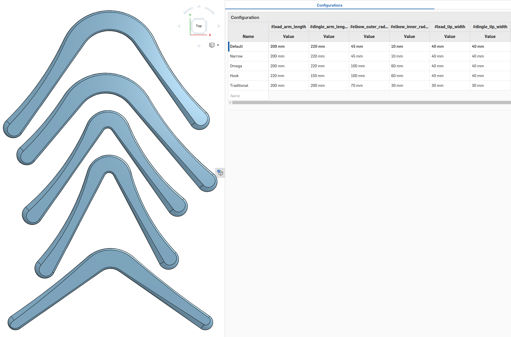
(Note: I'm cheating a little here – you usually wouldn't see all configurations of the part next to the configurations table. You can combine different combinations in an assembly, though, which is what I did here.)