The files for the boomerang described here can be found on Thingiverse.
There are a number of articles on this site about modeling 3d printable boomerangs in Blender, as well as a bunch of articles on modeling boomerangs in CAD.
Recently, I have learned about a great plugin for Blender called Sverchok, which is 'a powerful parametric tool for architects, allowing geometry to be programmed visually with nodes' (quote from Sverchok GitHub repo).
You can think of it as a parametric modeling environment for Blender, which lets you manipulate geometry not by pushing around vertices, but by specifying transformations of geometry through a node graph; this basically turns it into a kind of parametric CAD within Blender. Another way of viewing it is as "modifiers on steroids"; Sverchok nodes act a lot like modifiers, but can be combined in much more interesting ways.
This article basically reproduces the parametric CAD approach called "Lofting the Outline" from my CAD article. Thanks to Erindale Woodford, whose course on Sverchok was very helpful for this.
Drawing the Outlines
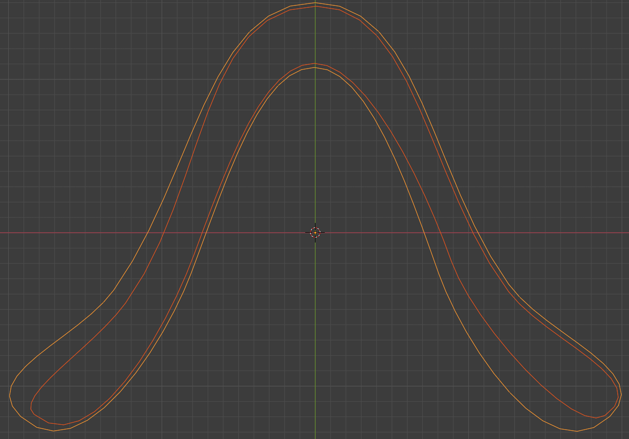
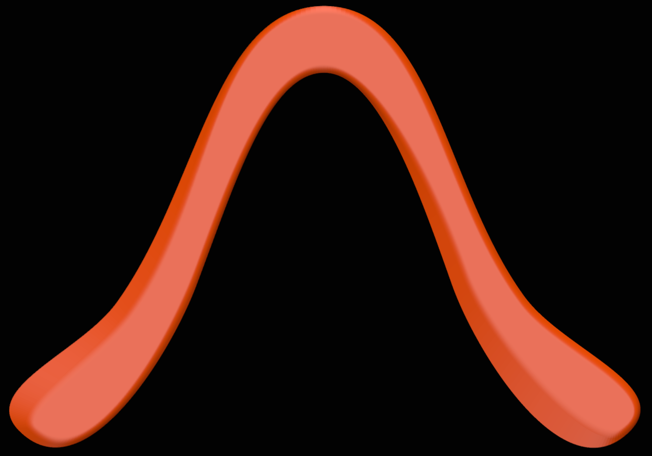
The basic idea is to draw two outlines: the overall outline of the boomerang as a whole, and an interior line representing the top surface of the boomerang (and thus the airfoil). Draw these in a reasonable size for your printer, say, with about 300 mm wingspan for a CR-10 style printer.
Draw those as Bezier circles and manipulate those circles into a boomerang shape in edit mode. Usually, I subdivide the circles once so I end up with 8 control points, which is plenty for most boomerang shapes.
Importing the Curves into Sverchok
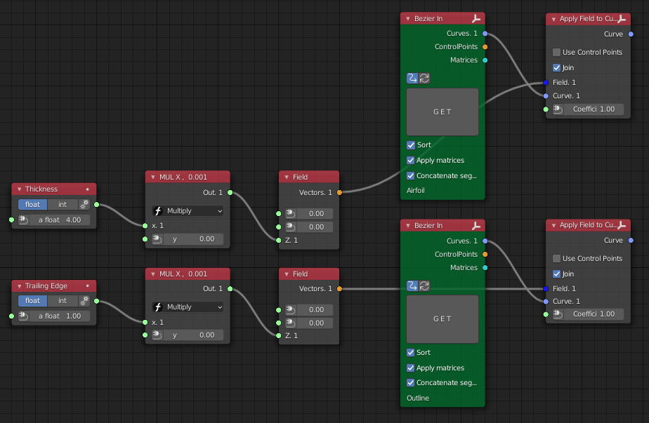
Import both curves into a new Sverchok node graph using "Bezier In" nodes. We need three curves in total: the outline, the outline translated about 1 mm upwards, and the interior line translated about 4 mm upwards. The translations can be accomplished using "Apply Field to Curve" nodes; the fields are just vectors like (0, 0, 0.001), i.e., a vector pointing 1 mm upwards.
The nodes on the left are just some scalar math for convenience, so that we can specify our thicknesses in scalars and millimeters, instead of vectors in meters.
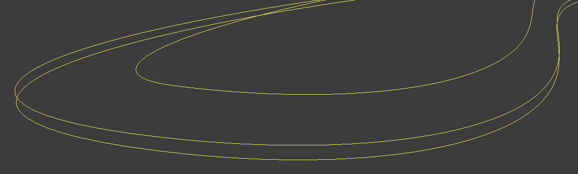
This is what the three curves should look like if we evaluate them individually.
Evaluating the Curves and Computing the Loft
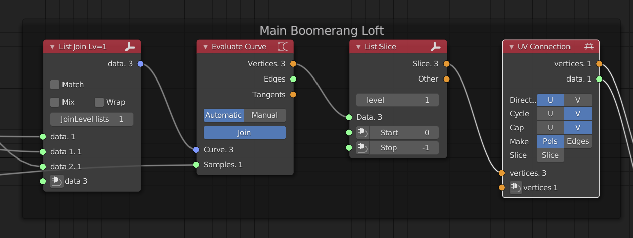
Now we need to join up these three curves, and turn them into one body. The idea is to put them into a list using a "List Join" node, and evaluate that list as a whole. This will yield a grid of points that we can turn into a surface using a "UV Connection" node as shown.
One final fix we need to employ is the list slice node. That one is needed to chop off one vertex of each curve, since the "Evaluate Curve" node will output the vertices at the seam of each circle twice.
Finalizing the Geometry
At this point, the top and bottom surfaces of our boomerang are inside out, as shown here:
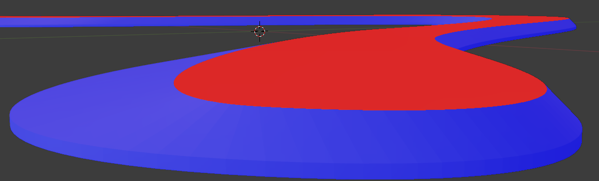
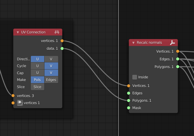
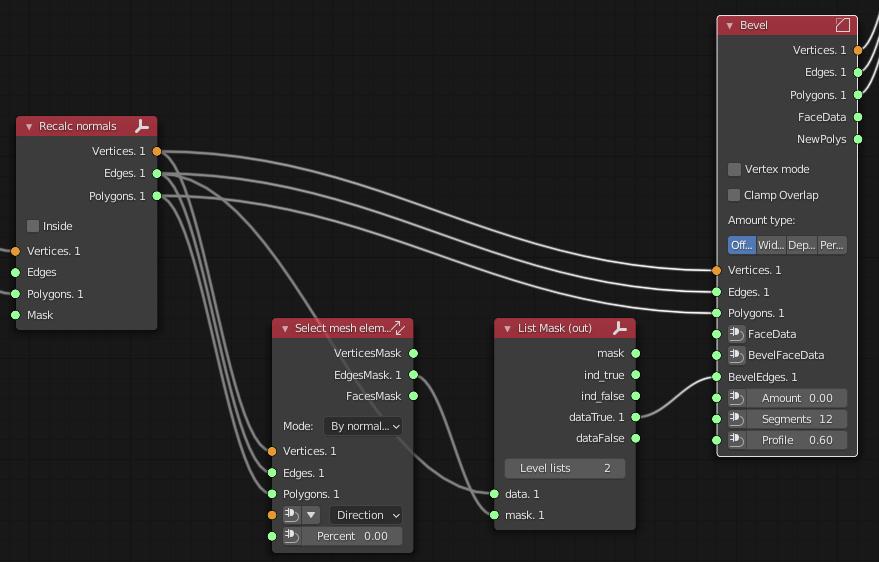
We can fix that with a "Recalc Normals" node. Furthermore, we select the top surface of our boomerang with a "Select Mesh Elements" node; from that, we use the edge mask to bevel the edge of the top surface, which will nicely round over our leading edges:

Final Result
This is our final result. The fun thing, as opposed to other ways of modeling a boomerang in Blender, is that we can now manipulate the Bezier outlines. The resulting boomerang shape, including the lofting, bevels etc., will update accordingly.