Introduction
In this tutorial, we will construct a parametric boomerang in FreeCAD. While in general, all the techniques shown in my previous article can be used, FreeCAD is a bit tricky in terms of usability, so I will demonstrate a way that lets us modify the boomerang shape after the fact with minimum hassle.
Outlines
The general idea is the one shown in the "lofting the outlines" approach from my previous tutorial.
So, we start with a sketch in FreeCAD and draw two outlines, one representing the overall shape and one the top surface of the boomerang. Here, I have used two periodic splines (i.e., closed loops that can be deformed using control points):
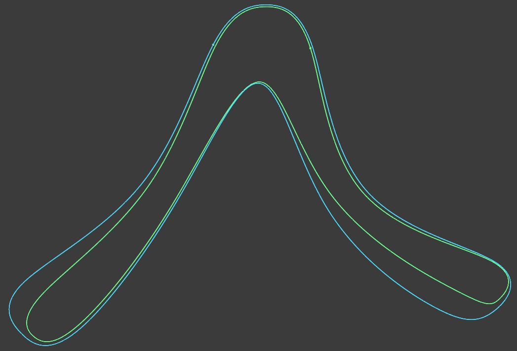
The idea is now to elevate the top outline a certain amount (say, 2.5 millimeters), and loft between the two outlines, thus creating a solid body with the desired airfoil.
Variables
In order to be able to modify some variables about our boomerang after the fact, we define those
in a spreadsheet. Change to the spreadsheet workbench, create a spreadsheet called Varsand
create values like this:
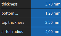
To be able to reference these values later, give each one an alias like thickness, airfoil_radius etc.
Shape Binders
This is the tricky part. We want to take the two curves, elevate the inner one and loft over those.
Confusingly, FreeCAD has several concepts that sound like they would enable this, like external geometry, carbon copy and possibly more. In my experience, those don't work as desired (e.g., carbon copy doesn't update when the original sketch is updated).
What we need instead are shape binders. Think of a shape binder as a reference to a bit of geometry that can be manipulated on its own.
For each of the two outlines, create a shape binder using this icon in the Part Design Workbench:

Select each outline in turn and create a shape binder for each.
Lofting the Main Shape
Now we need to move these shape binders into the third dimension. The main outline gets moved to a
height (z-value) that I called bottom_thickness.
To do that, select the respective shape binder in the tree view on the left, go to Data → Placement → Position → z. Here, we don't want to enter a numerical value directly, but rather reference the
value from our Vars spreadsheet. Enter the input field for the z value, hit the little f(x)
button on the right, and enter the reference to the spreadsheet like so: Vars.bottom_thickness It should autocomplete to <<Vars>>.bottom_thickness, but you can use the simpler form to enter it.
The shape binder for the top outline gets moved in the same fashion to the z coordinate of
<<Vars>>.thickness. We should now see two outlines – shape binders – a little ways apart, like so:
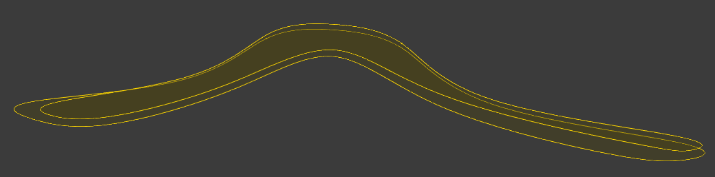
We're on the home stretch now. All we need to to is to loft over these two outlines, pad the shape towards the bottom, and fillet the leading edges. Select the two shape binders from the tree view, and hit the Additive Loft button. This should join the two outlines into a solid body as if stretching a rubber skin over both:
Completing the Airfoils
To complete the airfoil, we want to pad it towards the bottom to make it less sharp, and to round over ("fillet") the leading edges.
The former can be done using the Pad command. Select the bottom face of the boomerang, and pad it to
a length of <<Vars>>.bottom_thickness, referencing our spreadsheet as before.
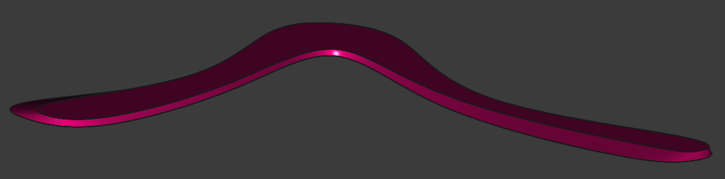
Our boomerang should now look something like this. Note the thickened trailing edges and the rounded leading edges:
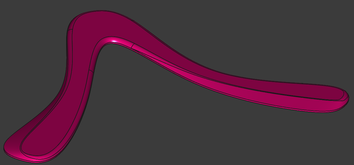
This shape is now ready to export (in the File menu) and 3d print!