Update: An even better approach using non-destructive modeling is available here.
Update: A new version of this for Blender 2.8 can be found here.
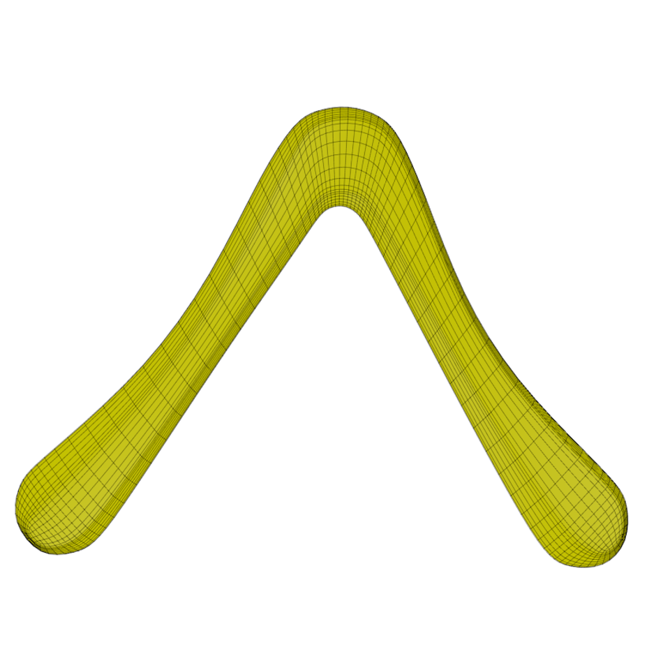
How to model this...
... so you can turn it into that:
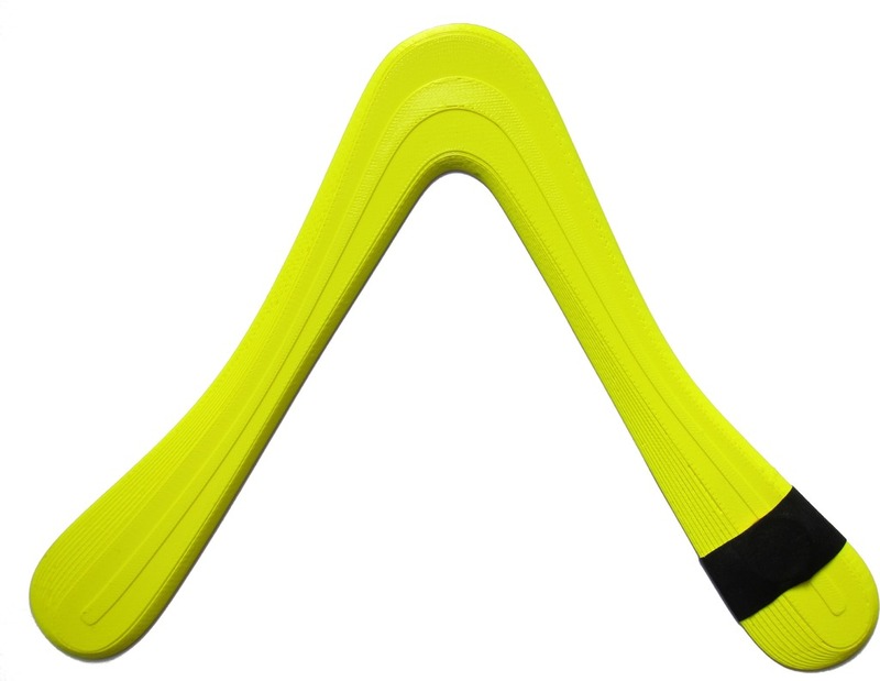
Recently, 3D printing has become so affordable that numerous companies offer 3D printed models at hobbyist prices. The obvious application for me was to create a printable boomerang model.
A while ago, I created a printable tri-blader using the trial version of a professional CAD tool. (A discussion of how to create boomerangs in CAD can be found in another article on this site.)
The boomerang worked reasonably well – I am too camera-shy to demonstrate it myself ;-), but luckily two people have printed that design and posted videos of the boomerang in flight on YouTube: video 1, video 2. Thanks guys!
So the boomerang worked, but I wanted to make one using open-source tools, which is why I tried Blender. While Blender is targeted at 3D visualization and animations, and not so much a CAD/CAM system, there are lots of powerful modeling tools in there. With Blender and some of the modeling techniques from William Vaughan's excellent book Digital Modeling, it's easy enough to create a workable boomerang shape for an actual, 3D-printed flying stick.
 The boomerang shown above can
be found on Thingiverse. I have had several prints of it made, ranging
from 18 cm wingspan to about 30 cm. All of them are reasonably good fliers,
even the small one which is almost pocket-sized. On one of the medium ones,
I taped a small coin (1 Euro cent) to increase range and wind stability,
which works really well.
The boomerang shown above can
be found on Thingiverse. I have had several prints of it made, ranging
from 18 cm wingspan to about 30 cm. All of them are reasonably good fliers,
even the small one which is almost pocket-sized. On one of the medium ones,
I taped a small coin (1 Euro cent) to increase range and wind stability,
which works really well.
Disclaimer 1: Note I'm by no means a professional engineer, nor have I ever worked professionally with CAD software, CNC tools, or some such. There are surely better ways to create 3D boomerang models, if you have the right tools and training. The model created here is ok, though, for playing with 3D modeling and printing.
Disclaimer 2: This is not a general Blender tutorial. There are plenty of those on the web. You might want to get acquainted a bit with Blender in general before trying to follow this tutorial.
Getting Started
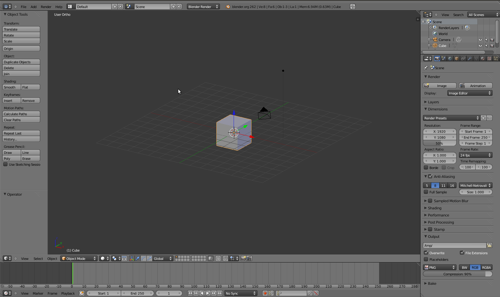 We start off with the default cube. Note that the size of the cube is
2x2x2 units.
We start off with the default cube. Note that the size of the cube is
2x2x2 units.
 I scale the cube to 20 x 20 x 0.4 units. That's about the volume that I
can use on the 3D printer if you assume that a unit is one centimeter.
I scale the cube to 20 x 20 x 0.4 units. That's about the volume that I
can use on the 3D printer if you assume that a unit is one centimeter.
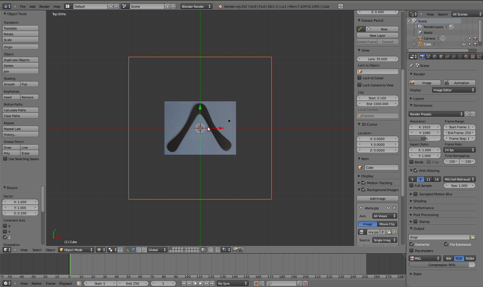 In the top ortho view, I add a background image. Making the cube
transparent (Z), I can now scale the background image to size (using the
"size" setting of the background image).
In the top ortho view, I add a background image. Making the cube
transparent (Z), I can now scale the background image to size (using the
"size" setting of the background image).
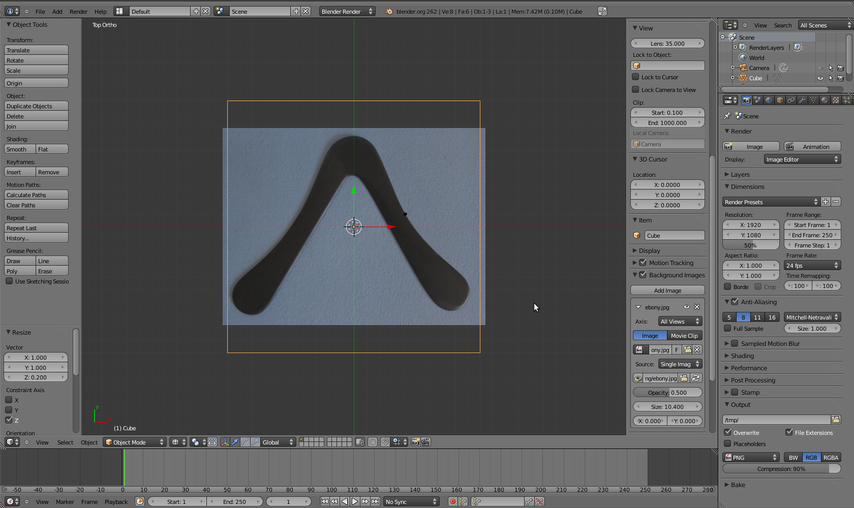 This looks about right. You could rotate the cube and squeeze out a
little more space for the boomerang. I don't worry about that now, and
scale the boomerang to final dimensions later using the printer
software.
This looks about right. You could rotate the cube and squeeze out a
little more space for the boomerang. I don't worry about that now, and
scale the boomerang to final dimensions later using the printer
software.
Drawing the Outline of the Boomerang
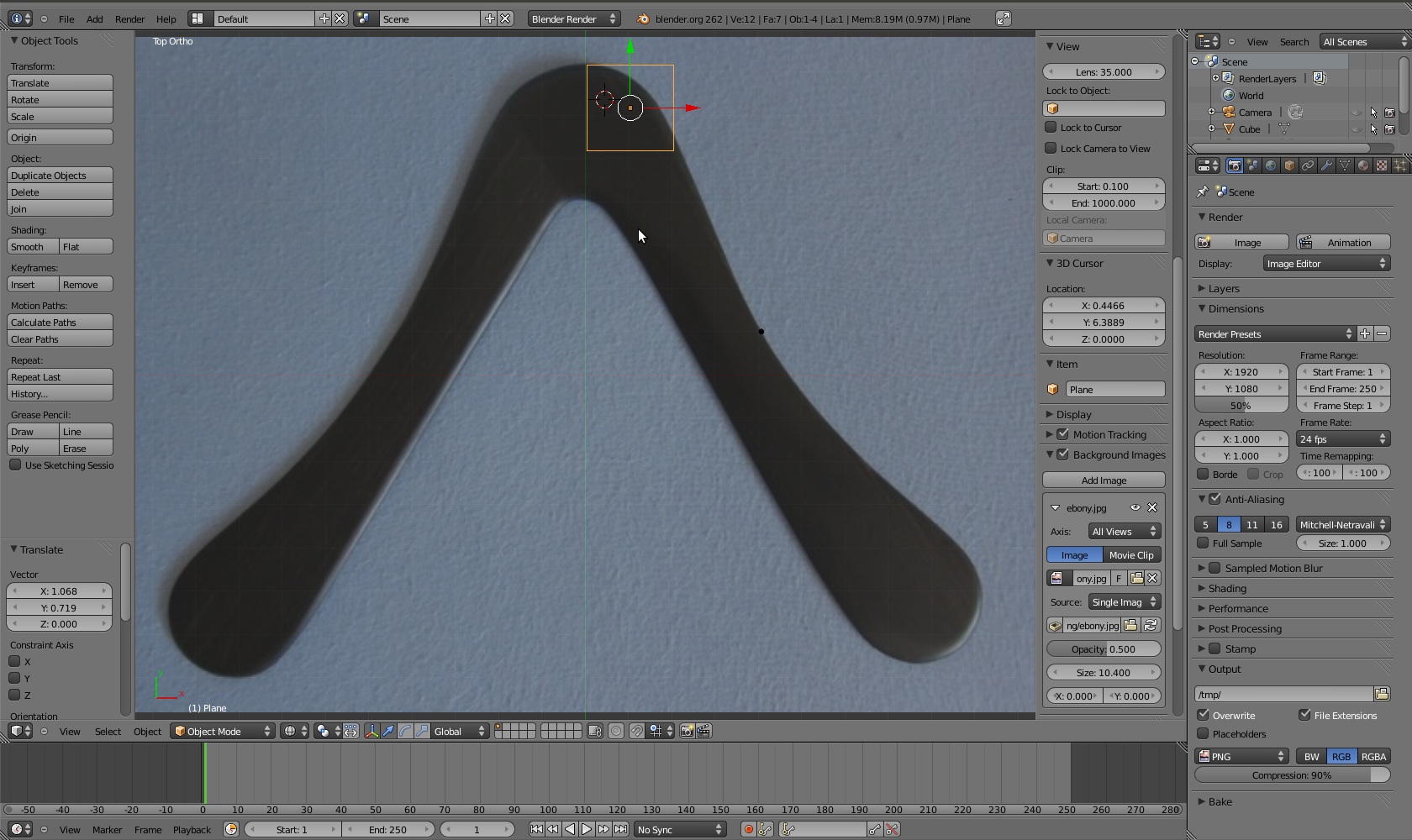 I start off modeling the boomerang by adding a plane (Shift-A). At this
point, I want to trace the outline of the boomerang with a number of
four-sided polygons ("quads").
I start off modeling the boomerang by adding a plane (Shift-A). At this
point, I want to trace the outline of the boomerang with a number of
four-sided polygons ("quads").
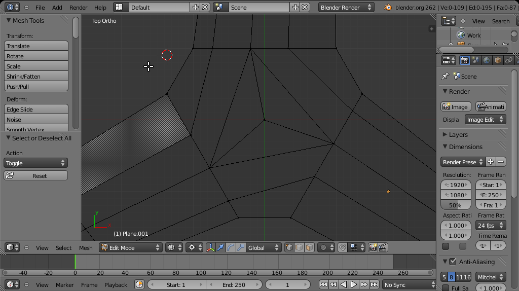
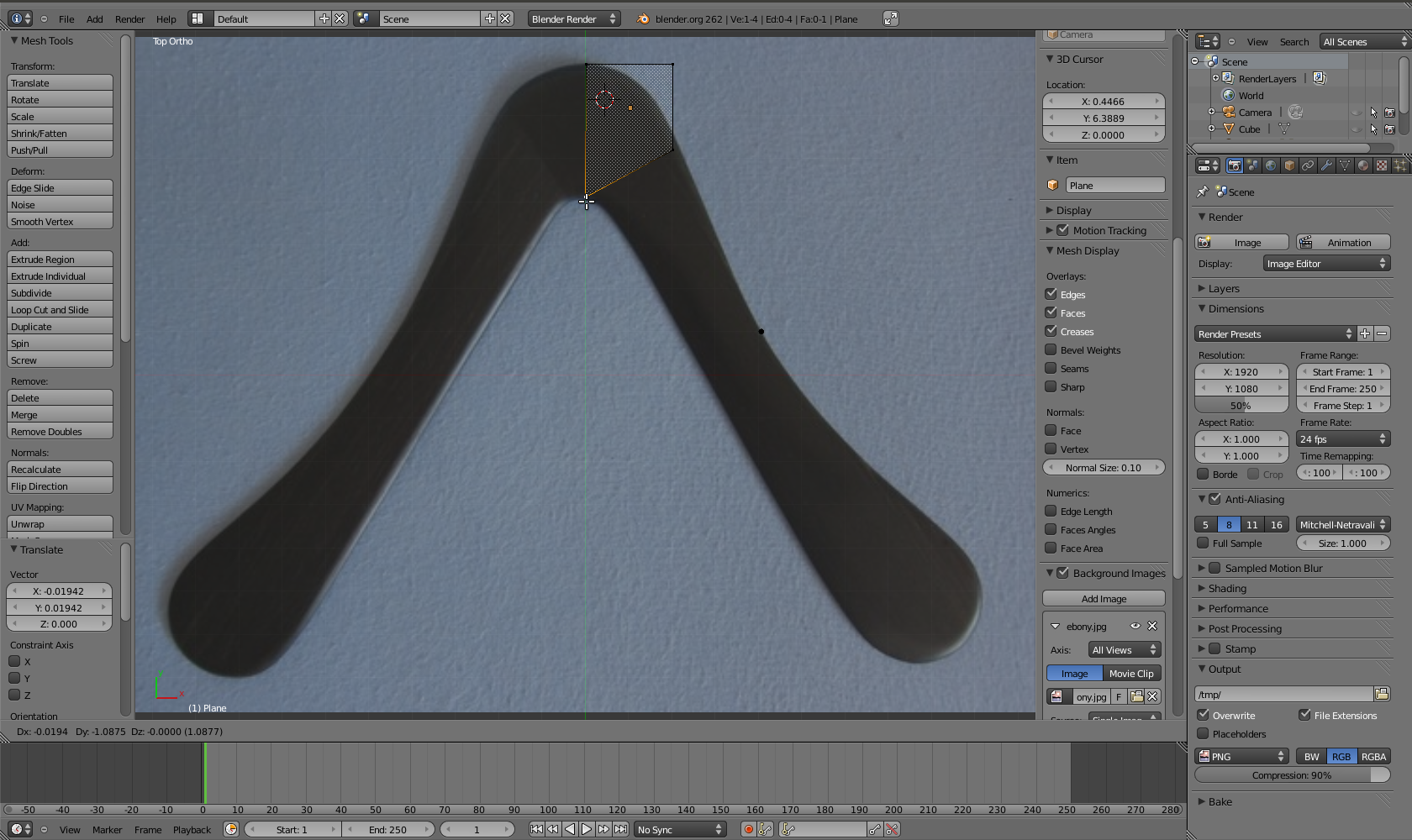 In edit mode (tab), I move the vertices (G) to follow the shape of the
boomerang.
In edit mode (tab), I move the vertices (G) to follow the shape of the
boomerang.
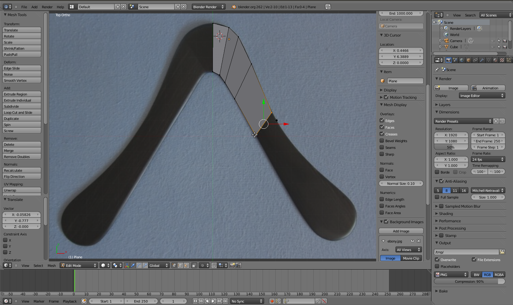
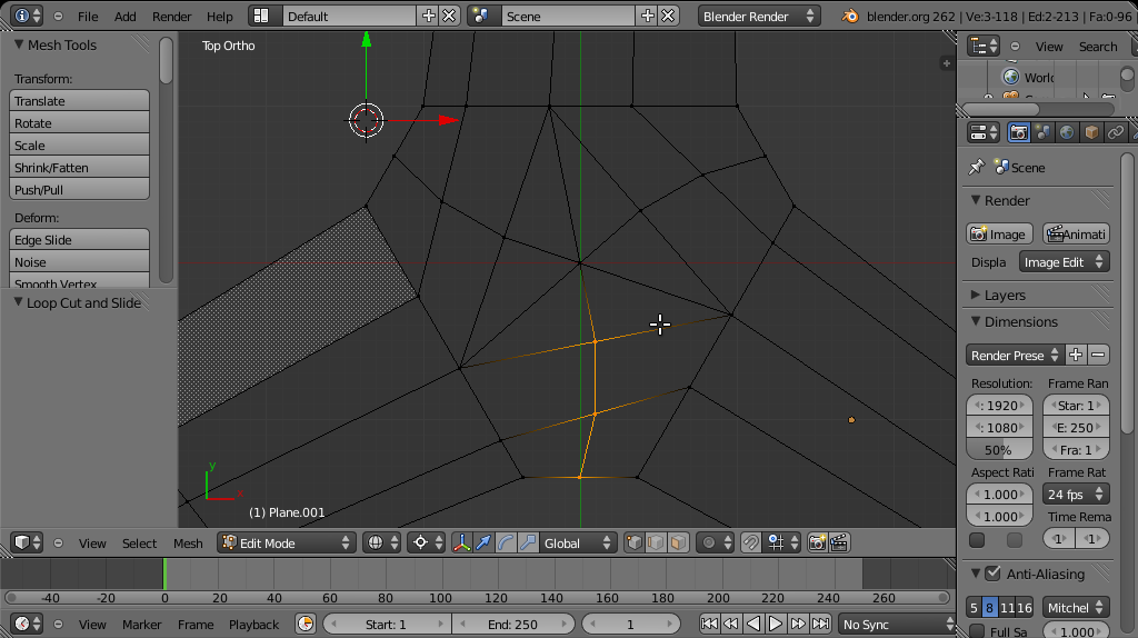
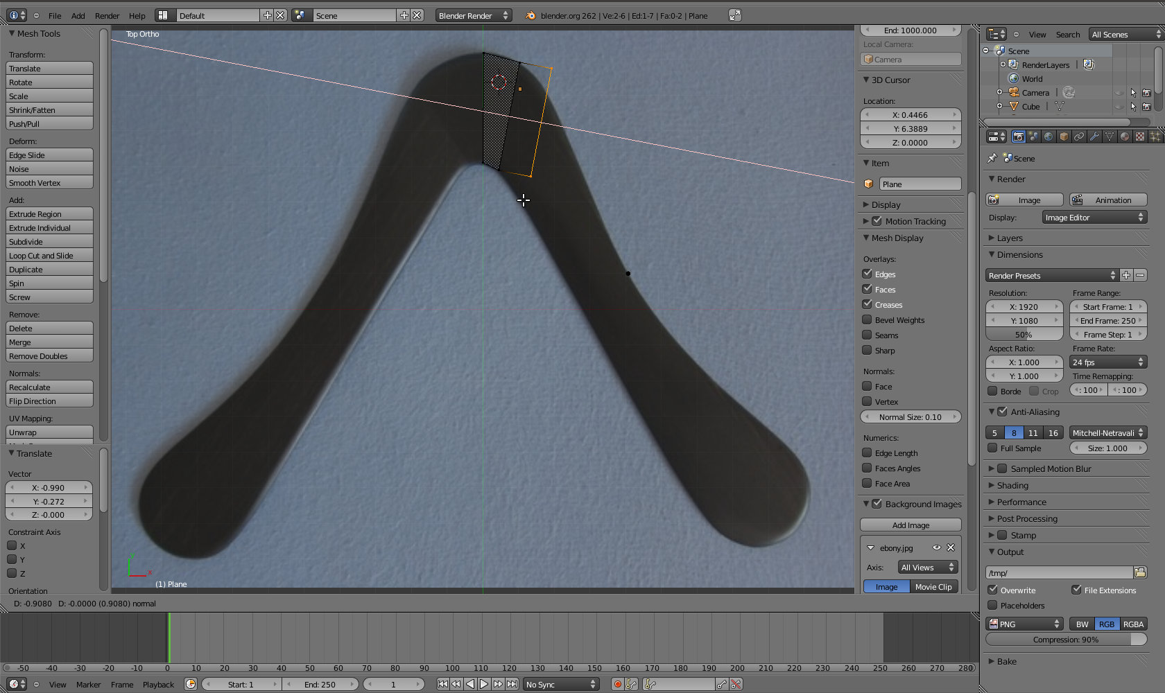 I extrude two vertices at a time (E). Afterwards, both can be scaled
(S), moved (G) and rotated (R) at the same time or separately.
I extrude two vertices at a time (E). Afterwards, both can be scaled
(S), moved (G) and rotated (R) at the same time or separately.
 Notice where the shape needs more detail and where it doesn't. This may
look a little rough right now, but we'll fine-tune the shape later.
Notice where the shape needs more detail and where it doesn't. This may
look a little rough right now, but we'll fine-tune the shape later.
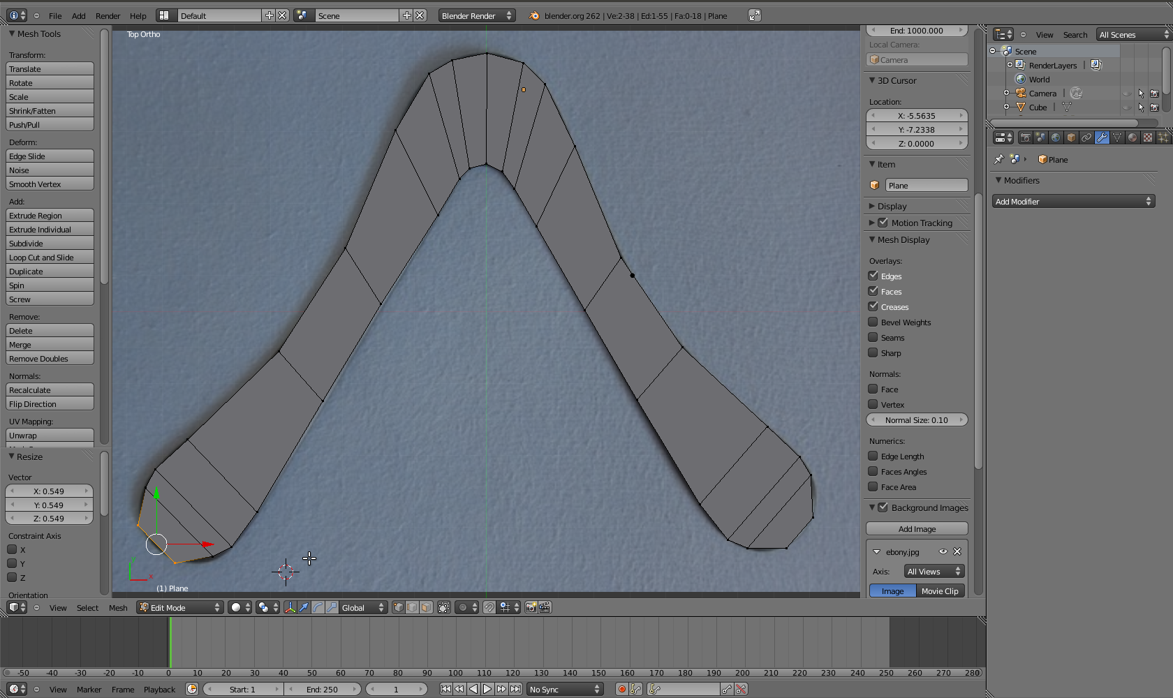 I walk around the whole boomerang, trying to keep the topology
approximately symmetric.
I walk around the whole boomerang, trying to keep the topology
approximately symmetric.
Airfoils and Topology Repairs
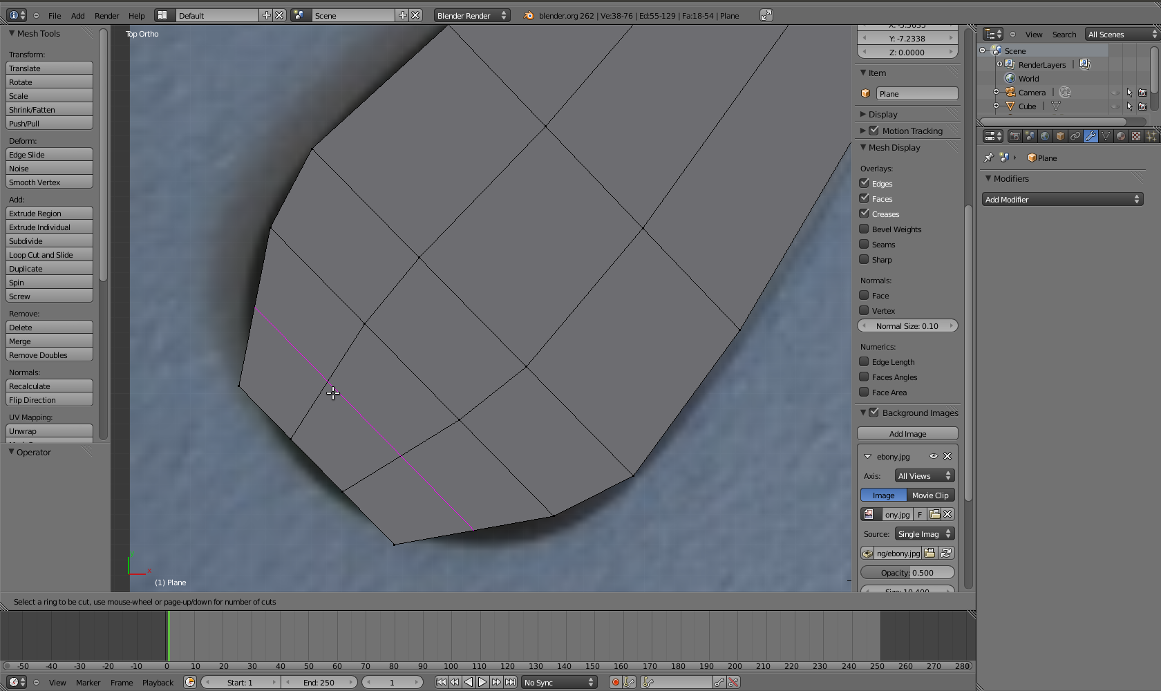
 To be able to create a leading and trailing edge later, I add two loop
cuts (Ctrl-R). In order for this to work, our topology needs to be a
chain of quads that runs consecutively from one end of the boomerang to
the other.
To be able to create a leading and trailing edge later, I add two loop
cuts (Ctrl-R). In order for this to work, our topology needs to be a
chain of quads that runs consecutively from one end of the boomerang to
the other.
 Before we can create the airfoils, we need to change the topology near
the wing tips. We want the leading and trailing edges to flow around the
whole boomerang, somewhat like a tapeworm.
Before we can create the airfoils, we need to change the topology near
the wing tips. We want the leading and trailing edges to flow around the
whole boomerang, somewhat like a tapeworm.
 We need some more topology here, so I create another loop cut (Ctrl-R).
 The idea is to merge the corner vertex with its left and right
neighbors.
The idea is to merge the corner vertex with its left and right
neighbors.
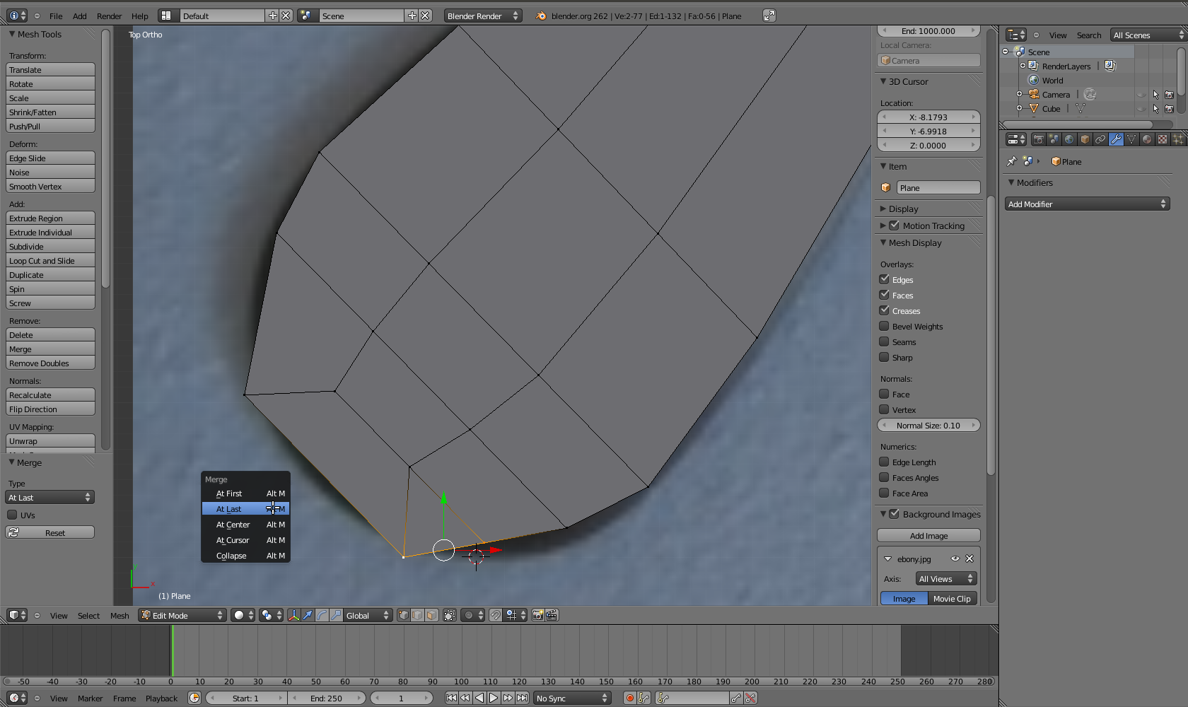 To do that, hit alt-M and "Merge at first" or "Merge at last", depending
on where the resulting vertex should be.
To do that, hit alt-M and "Merge at first" or "Merge at last", depending
on where the resulting vertex should be.
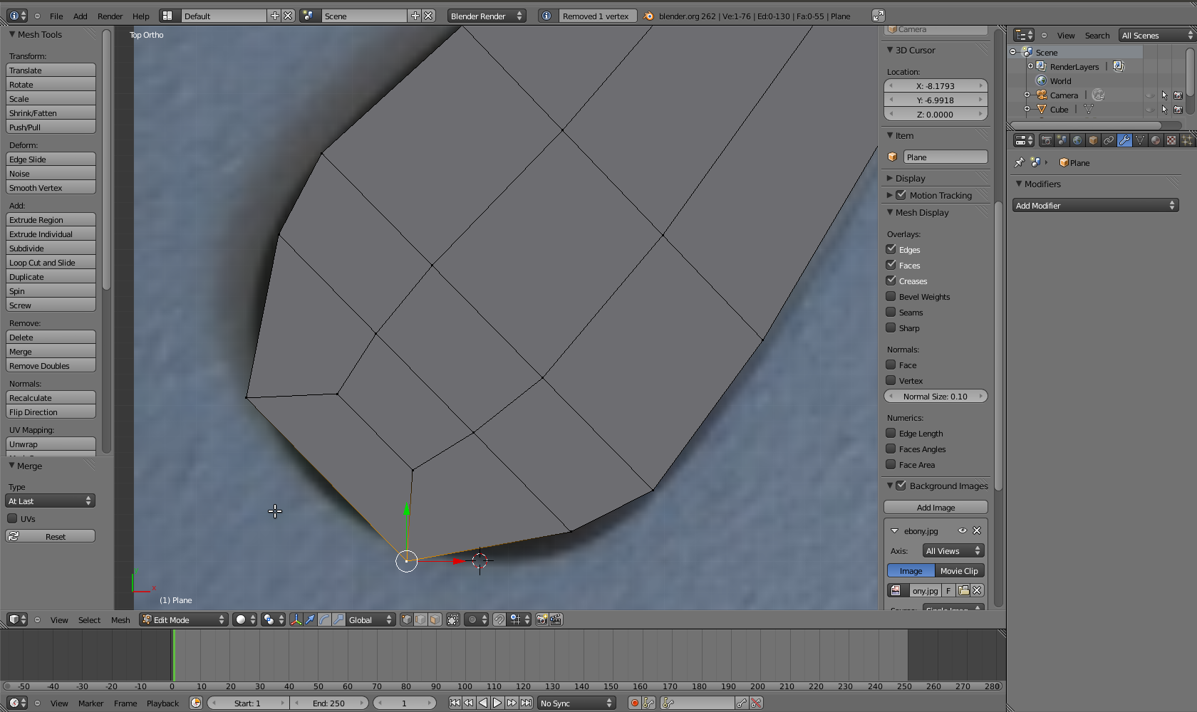 The finished wing tip, ready to have airfoils added.
 Here's the difference between the repaired wingtip (dingle) and the
original one (lead). We want the lead to look like the dingle.
Here's the difference between the repaired wingtip (dingle) and the
original one (lead). We want the lead to look like the dingle.
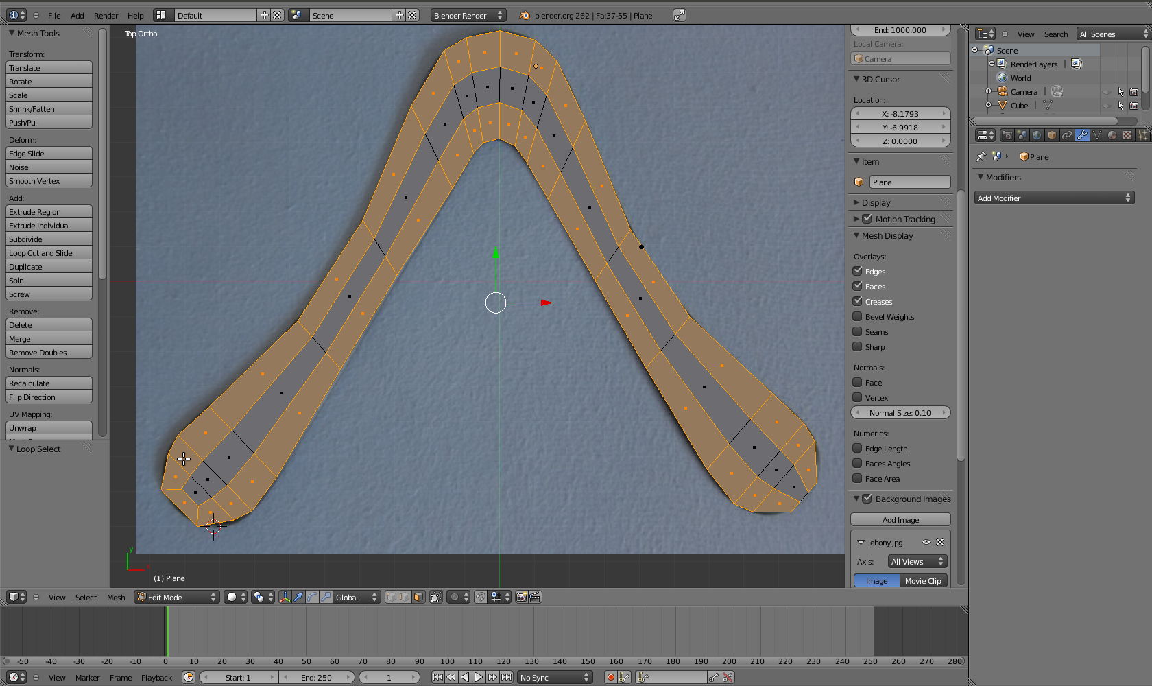
 After repeating the topology repair on the lead wingtip, we can see our
airfoils.
After repeating the topology repair on the lead wingtip, we can see our
airfoils.
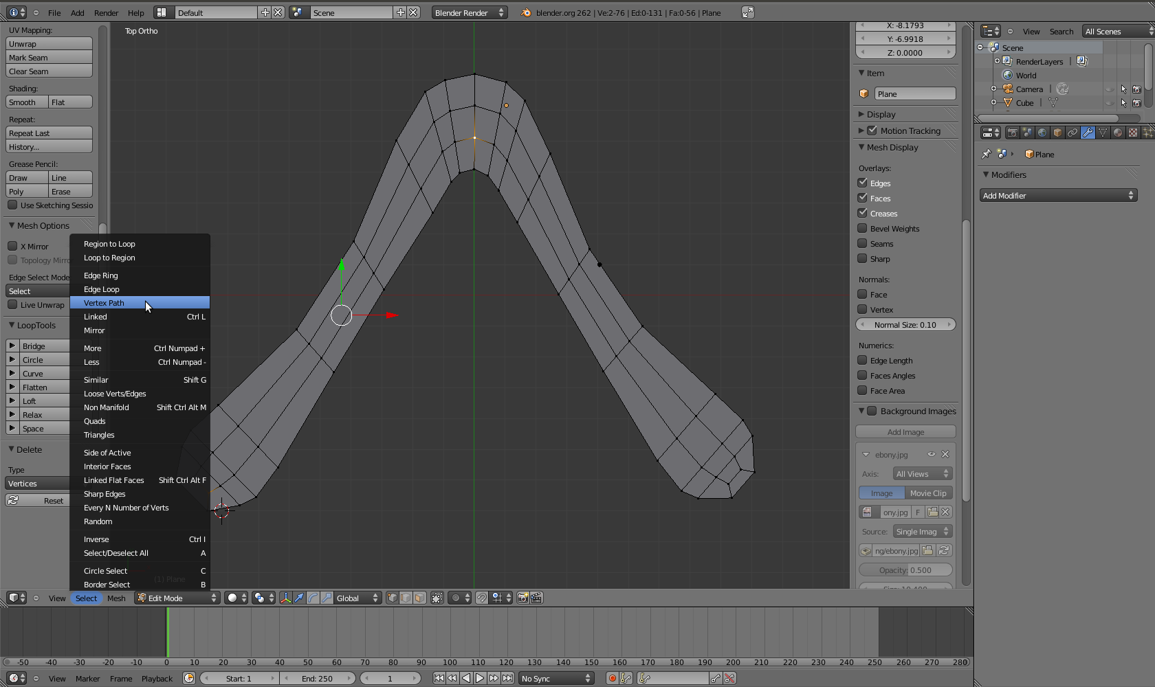 We now need to move around the leading and trailing edges a bit. With
two vertices selected, I can use "Vertex Path" from the "Select" menu to
select the path in between.
We now need to move around the leading and trailing edges a bit. With
two vertices selected, I can use "Vertex Path" from the "Select" menu to
select the path in between.
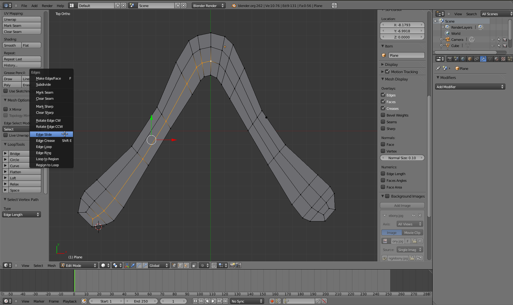 Here's our leading edge. We can now move it to the front of the wing
using "Edge Slide" from the edge menu (Ctrl-E).
Here's our leading edge. We can now move it to the front of the wing
using "Edge Slide" from the edge menu (Ctrl-E).
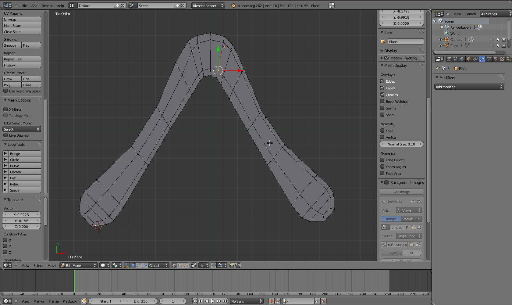 In the same fashion, the other leading edge and the two trailing edges
were created. The vertices near the elbow and the wingtips may need to
be dragged around manually (G).
In the same fashion, the other leading edge and the two trailing edges
were created. The vertices near the elbow and the wingtips may need to
be dragged around manually (G).
 The flat boomerang ready to be extruded in the third dimension.
Going 3D
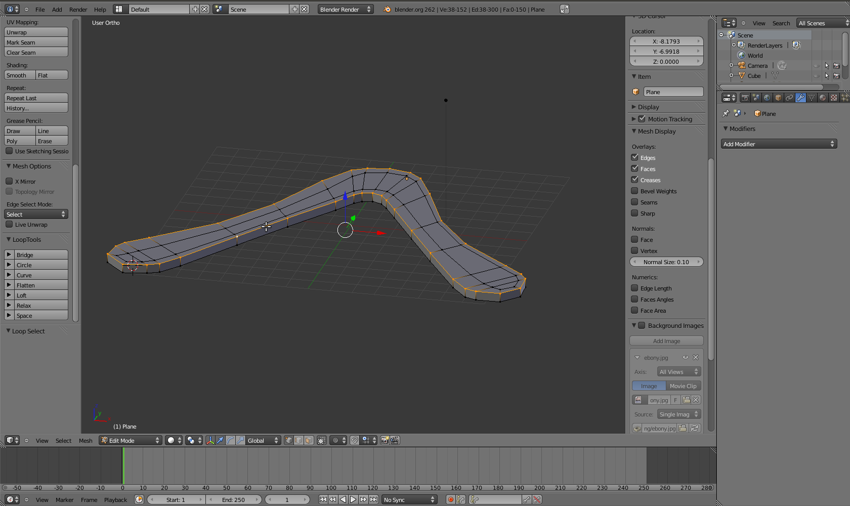
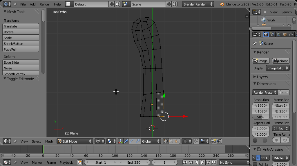
 With all vertices selected, the shape can be extruded 0.4 units (4
millimeters) in the Z direction (Z). Constrain the extrusion to that
direction.
With all vertices selected, the shape can be extruded 0.4 units (4
millimeters) in the Z direction (Z). Constrain the extrusion to that
direction.
 We can now select a vertex loop around the edges (Shift-alt right mouse
button).
We can now select a vertex loop around the edges (Shift-alt right mouse
button).
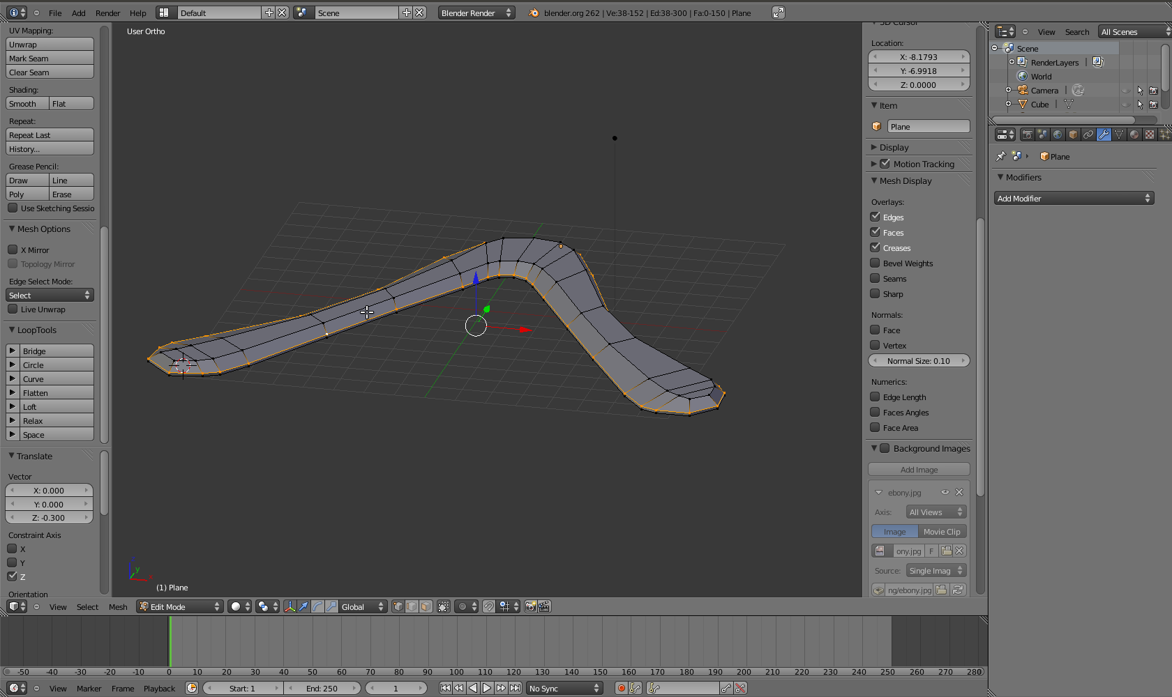 The vertex loop gets moved along the -Z axis, say 3 millimeters (0.3
Blender units).
The vertex loop gets moved along the -Z axis, say 3 millimeters (0.3
Blender units).
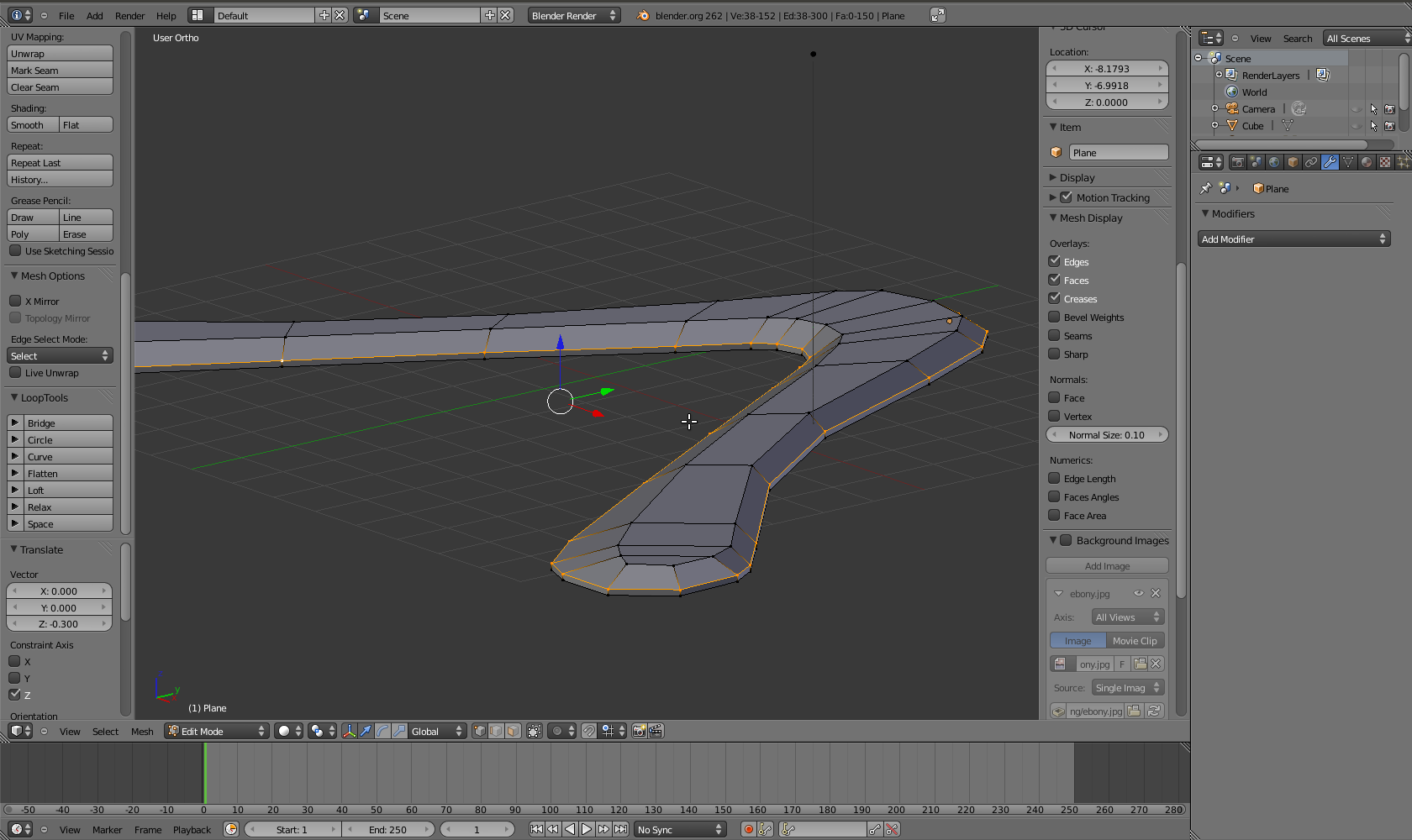 From a different perspective, the airfoil can be seen.
Smoothing and Final Shaping
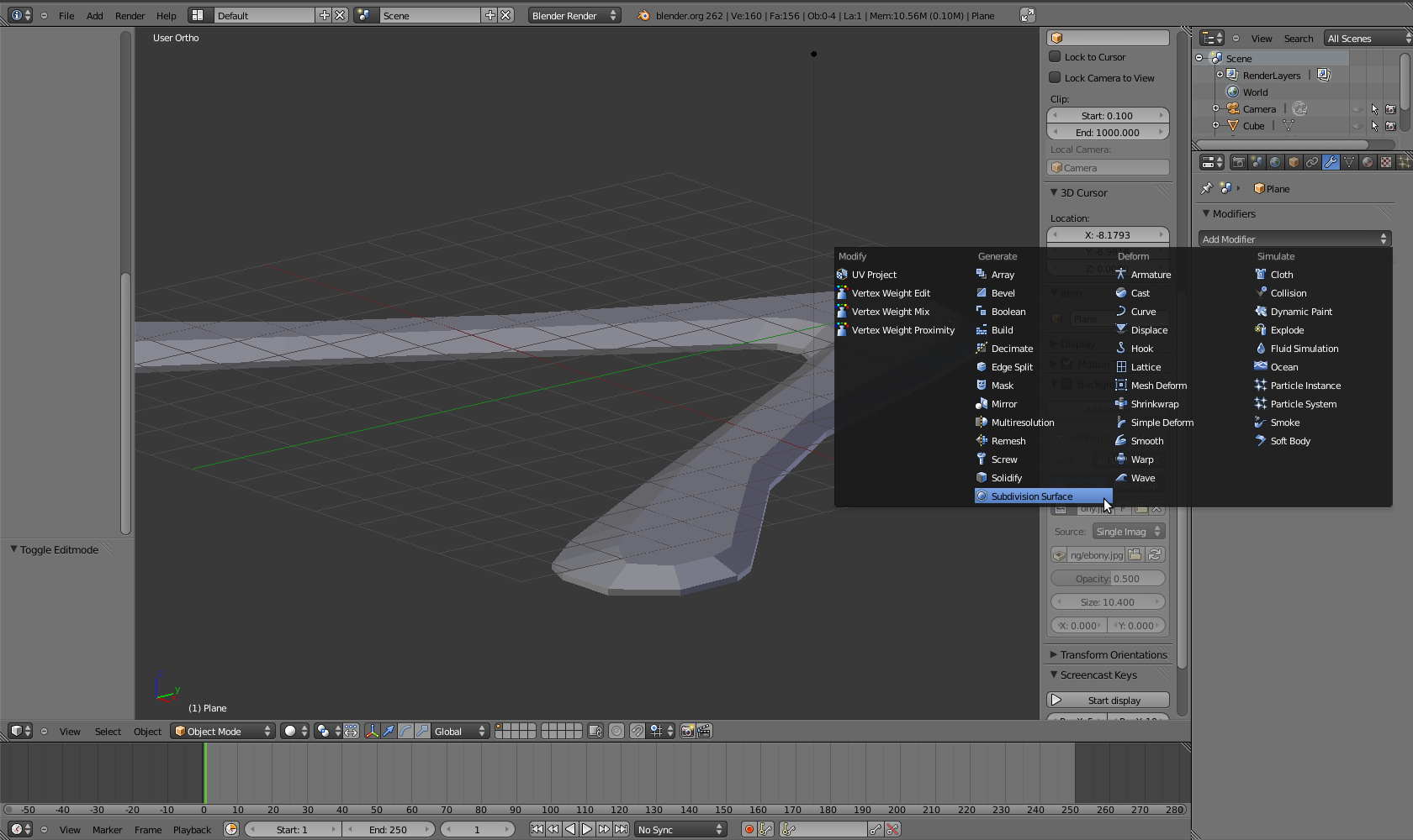 So far, the boomerang looks quite rough. This can be fixed by using a
subdivision surface modifier. It's in the menu with the little spanner
on the right.
So far, the boomerang looks quite rough. This can be fixed by using a
subdivision surface modifier. It's in the menu with the little spanner
on the right.
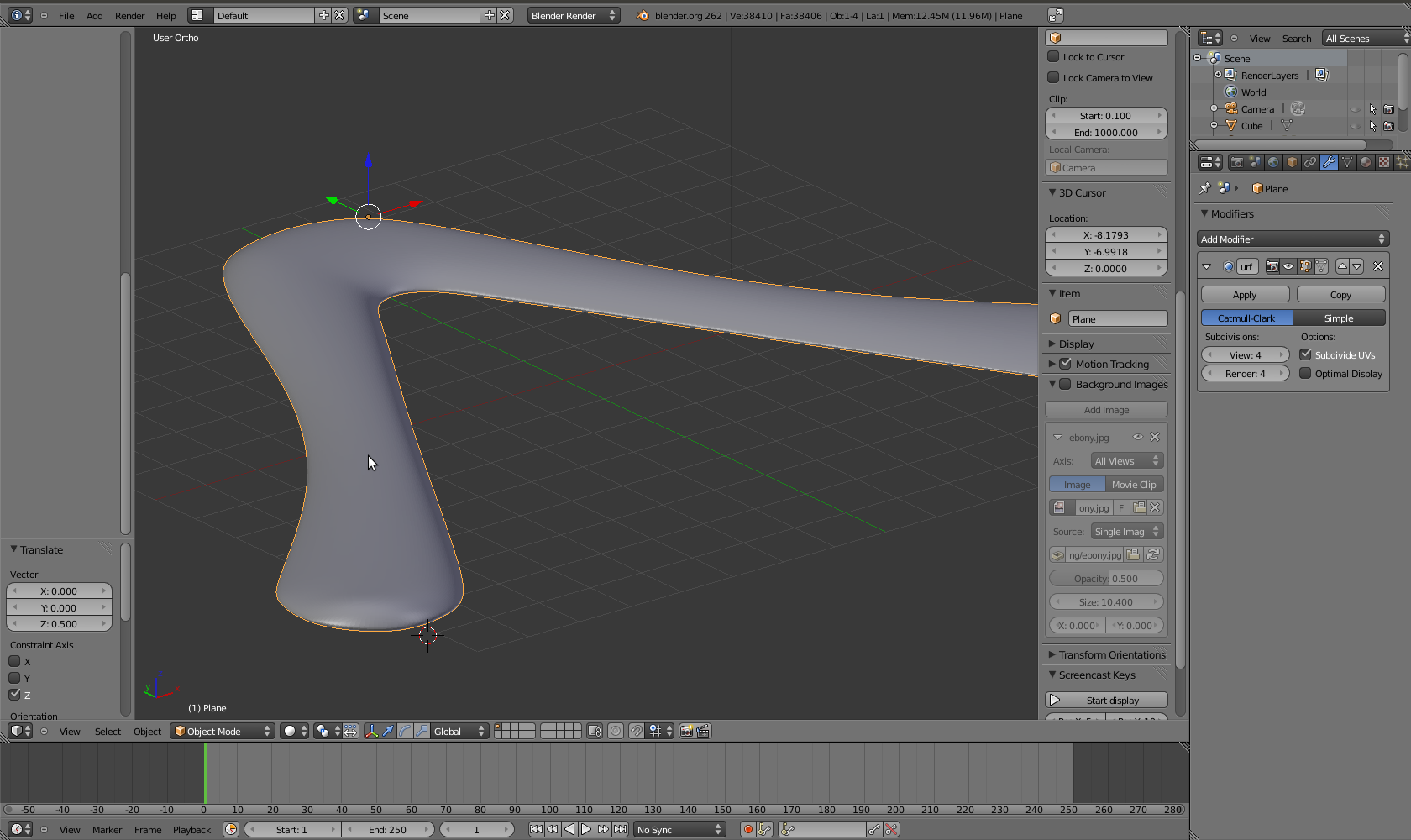 Now this looks like a boomerang!
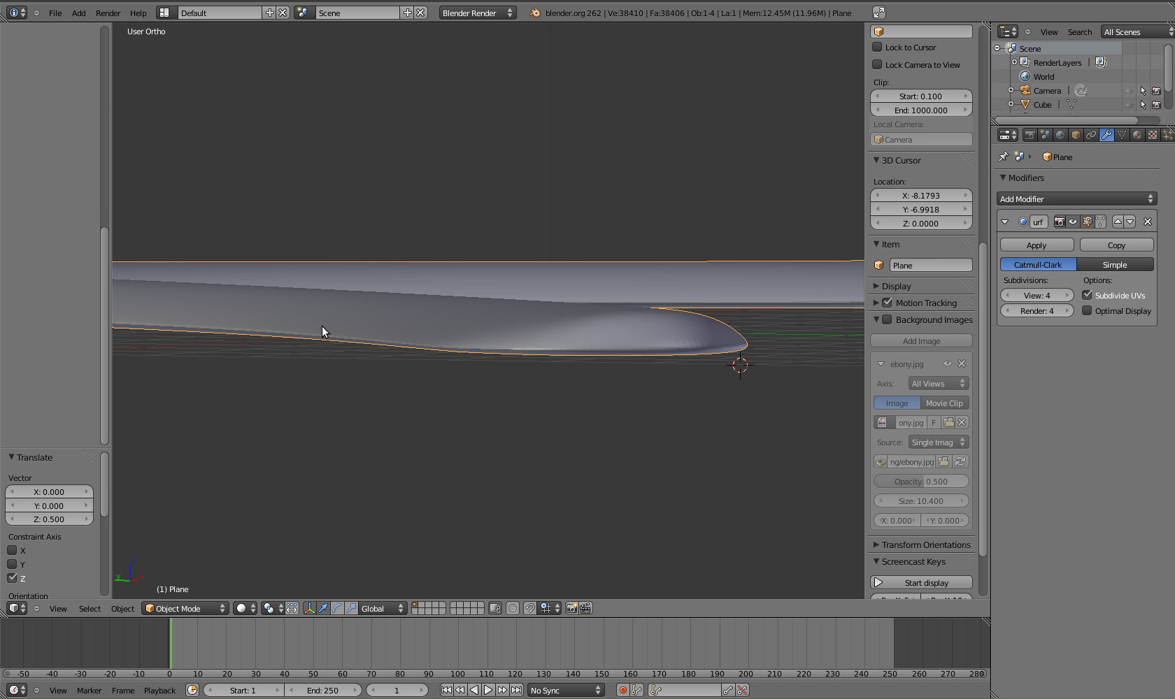 The airfoil is not too bad, but I like to make it a little more defined.
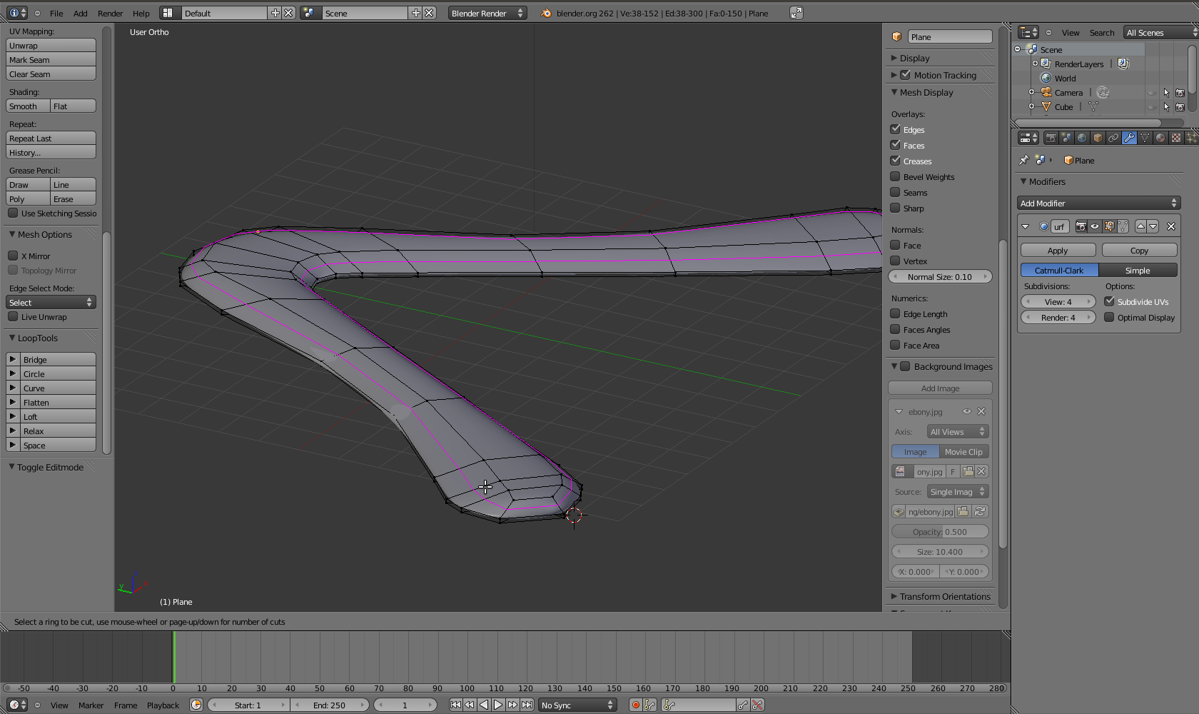 To keep the subsurf modifier from rounding the top too much, another
edge loop is created (Ctrl-R). This keeps the top from being rounded
over.
To keep the subsurf modifier from rounding the top too much, another
edge loop is created (Ctrl-R). This keeps the top from being rounded
over.
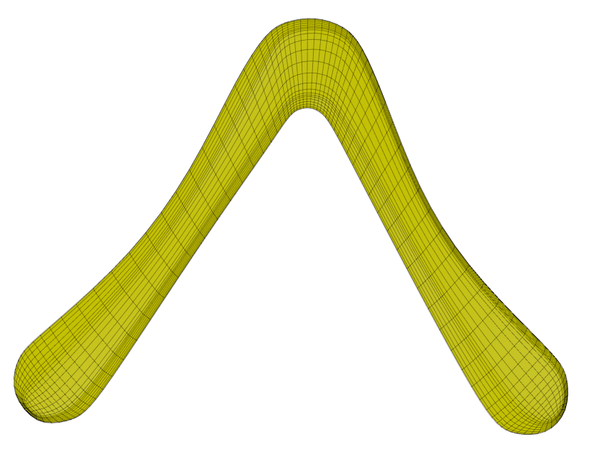
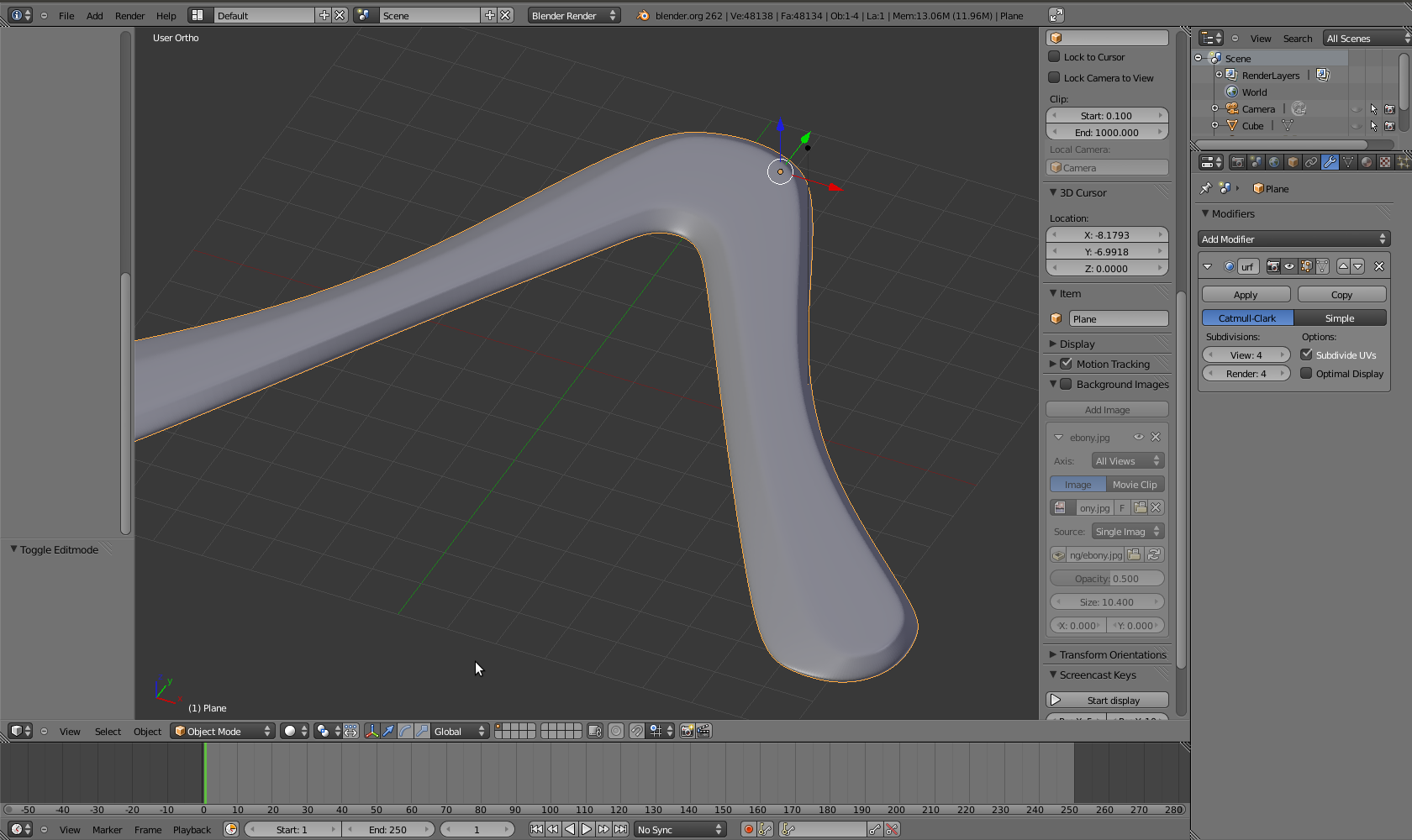 That's our finished boomerang! Note that the modifier is just applied on
the fly, the original geometry is still intact. This means vertices can
still be moved around to fix the shape, and the resulting geometry will
be smoothed again by the modifier.
That's our finished boomerang! Note that the modifier is just applied on
the fly, the original geometry is still intact. This means vertices can
still be moved around to fix the shape, and the resulting geometry will
be smoothed again by the modifier.
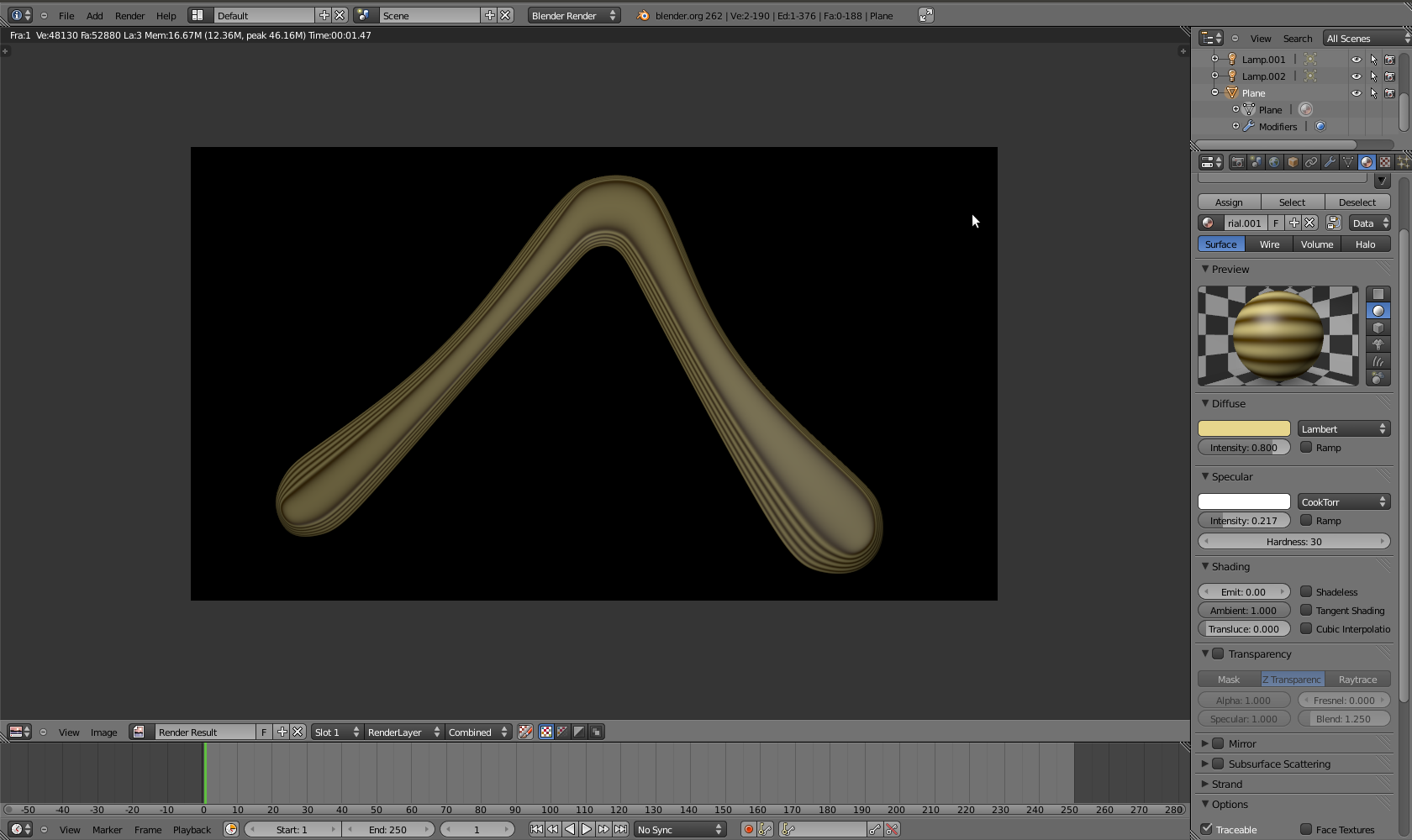 Put on some baltic birch texture, and verify that this actually looks
like a boomerang.
Put on some baltic birch texture, and verify that this actually looks
like a boomerang.
Appendix: Modeling a Tri-Blader
 The same techniques described above will also work for tri-bladers.
Let's assume we already have one wing modeled as described
above, including the airfoils.
The same techniques described above will also work for tri-bladers.
Let's assume we already have one wing modeled as described
above, including the airfoils.
 Place three copies of the wing around the 3D cursor. It helps to center
it first (Shift-C). Then duplicate (Shift-D) and rotate by 120 degrees
(R 120). The copies need to be joined (Ctrl-J) into one object.
Place three copies of the wing around the 3D cursor. It helps to center
it first (Shift-C). Then duplicate (Shift-D) and rotate by 120 degrees
(R 120). The copies need to be joined (Ctrl-J) into one object.
 Connecting the leading and trailing edge is easy. Just go to edge select
mode, select opposite edges, and fill with faces (F).
Connecting the leading and trailing edge is easy. Just go to edge select
mode, select opposite edges, and fill with faces (F).
 To fill the middle, select the vertices of the inner triangle, extrude
them (E) and merge at center (alt-M).
To fill the middle, select the vertices of the inner triangle, extrude
them (E) and merge at center (alt-M).
 We could probably get away with this, but in general, it is advisable to
avoid triangular faces. In order to repair these, add some loop cuts
(Ctrl-R). This yields even more triangles, which we'll fix next.
We could probably get away with this, but in general, it is advisable to
avoid triangular faces. In order to repair these, add some loop cuts
(Ctrl-R). This yields even more triangles, which we'll fix next.
 We can now pick pairs of triangles and join them into diamonds (alt-J).
Now we should be back to a topology that consists only of quads.
We can now pick pairs of triangles and join them into diamonds (alt-J).
Now we should be back to a topology that consists only of quads.
 The rest works as in the two-blader case: extrude, define the airfoil,
put on a subsurf modifier. This leaves us with a nice polygon flow,
without nasty surprises in the airfoils around the center of the
boomerang.
The rest works as in the two-blader case: extrude, define the airfoil,
put on a subsurf modifier. This leaves us with a nice polygon flow,
without nasty surprises in the airfoils around the center of the
boomerang.